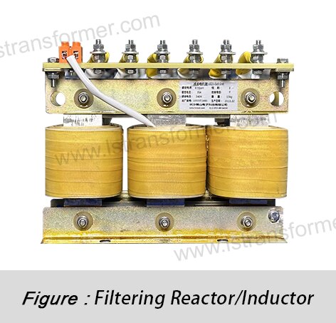
Does the Shortened Lifespan of Reactors in High-Temperature Environments? —Dual Optimization Strategy: Materials and Heat Dissipation
Does the Shortened Lifespan of Reactors in High-Temperature Environments?
—Dual Optimization Strategy: Materials and Heat Dissipation
Against the backdrop of global energy transition and accelerated industrial intelligence, reactors, as critical components of power systems, have seen their reliability and lifespan become a growing focus for equipment manufacturers, grid operators, and industrial users. High-temperature environments are widely recognized as a major accelerator of power equipment aging, making effective countermeasures against temperature-induced lifespan degradation a core challenge for the industry. This article delves into the mechanisms of high-temperature impacts based on international standards and engineering practices, proposing a dual optimization strategy focusing on materials and heat dissipation.
Content
1. How High Temperatures "Burn" Reactor Lifespan: A Warning from the Arrhenius Equation
The lifespan of a reactor hinges on the durability of its organic insulating materials (e.g., epoxy resin, Nomex® paper, impregnated varnish). High temperatures trigger molecular chain breakage, accelerated oxidation, and intensified partial discharges, significantly hastening irreversible aging.
● Core equation for quantifying aging rates: The Arrhenius Equation
The relationship between lifespan (L) and absolute temperature (T) is expressed as:
L = A * exp(Ea / (k * T))
L: Expected lifespan
A: Material-specific constant
Ea: Activation energy for material aging (eV)
k: Boltzmann constant (8.617333262145 × 10⁻⁵ eV/K)
T: Absolute temperature (K)
Intuitive impact of temperature: The 10°C Rule
According to IEEE Std C57.96 and IEC 60076-7, empirical studies show that for every 6-10°C sustained increase in operating temperature, the expected lifespan of an insulation system is halved. For example, an H-class insulation system (designed for 180°C) operating continuously at 190°C may see its lifespan reduced to just 50% of its design value.
Insulation Class | Nominal Temp (℃) | Hotspot Limit (℃) | Lifespan Benchmark | Temp Index TI (℃) |
B (130) | 130 | 140 | ~20 years | ≥130 (≥20,000 hrs) |
F (155) | 155 | 175 | ~20 years | ≥155 (≥20,000 hrs) |
H (180) | 180 | 195 | ~20 years | ≥180 (≥20,000 hrs) |
C (>180) | >180 | >195 | Material-dependent | ≥200 (≥20,000 hrs) |
Table 1: Insulation Material Classes and Temperature-Lifespan Relationships
(Based on IEC 60085, IEEE Std C57.12.00)
2. Material Optimization: Building High-Temperature-Resistant "Genes"
The high-temperature resilience of reactors fundamentally depends on the molecular stability of their insulating materials. Traditional organic materials (e.g., Class A/B insulation) are prone to molecular chain breakage, oxidative cracking, and partial discharges under sustained high temperatures, leading to irreversible insulation degradation. Modern material science has broken through thermal limits via three key approaches, enabling reactors to achieve extended lifespans even in extreme environments.
●Upgrading to High-Temperature Insulation Material Systems
●Material Selection
(1)(Polyimide film (Kapton®):Glass transition temperature (Tg) >360°C, thermal decomposition temperature >500°C, with aromatic rings and imide bonds providing ultra-high stability.
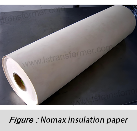
(2)Nomex® aramid paper:Long-term heat resistance up to 220°C, with hydrogen bond networks maintaining mechanical strength at high temperatures.
(3) Silicone resin impregnation systems:Operational range of -50°C to +250°C, with Si-O bond energy (452 kJ/mol) far exceeding C-C bonds (346 kJ/mol).
●Failure Mode Comparison
(1)Traditional epoxy resin:Suffers "thermal oxidative degradation" above 180°C, with random molecular chain breakage causing a sharp rise in dielectric loss factor (tanδ).
(2)Modified epoxy/organosilicon hybrid materials:Incorporates siloxane segments to form Si-O-Si crosslinked networks at high temperatures, delaying degradation.
●Engineering Validation Data
IEEE 117 test (accelerated aging): H-class modified epoxy showed only a 12% drop in breakdown voltage after 10,000 hours at 200°C, versus >40% for traditional materials.
●Nanocomposites: Synergistic Enhancement of Thermal Conductivity and Dielectric Properties
Filler Type | Thermal Conductivity (W/mK) | Dielectric Constant (ε) | Optimal Doping Ratio | Primary Role |
Al₂O₃ | 30-40 | 9-10 | 3-5 wt% | Boosts thermal conductivity, suppresses electrical treeing |
BN | 300-400 | 4-5 | 1-3 wt% | Anisotropic heat dissipation, reduces dielectric loss |
SiC | 120-150 | 6-7 | 2-4 wt% | Field homogenization, minimizes partial discharges |
●Mechanism
(1)Thermal path optimization:Nanoparticles form "thermal percolation networks" in the matrix, raising composite thermal conductivity from 0.2 W/mK to 0.6-1.2 W/mK (3-6x improvement).
(2)Electrical treeing suppression:Nanoparticles act as "trap centers" to capture high-energy electrons, delaying insulation degradation (experiments show 20-30% higher partial discharge inception voltage, PDIV).
●Manufacturing Keys
(1)Dispersion technology:Ultrasonic treatment + silane coupling agent modification to prevent nanoparticle agglomeration (agglomerates >100nm cause field distortion).
(2)Curing process:Gradient temperature curing (e.g., 80°C→120°C→160°C) ensures uniform filler distribution.
● Vacuum Pressure Impregnation (VPI) and Encapsulation Innovations
Traditional issue: Air gaps between winding layers cause localized overheating (temperature differences of 15-20°C), accelerating insulation aging.
●VPI liquid silicone technology
(1)Process parameters:Vacuum <1 mbar, pressure 0.5-0.8 MPa, ensuring silicone penetration into micron-scale pores.
(2)Advantages:Post-curing, the coefficient of thermal expansion (CTE) matches copper windings, preventing thermal cycling stress cracks.
●Case comparison
(1)Non-impregnated reactor: After 1 year at 150°C, partial discharge levels rose from 5pC to 50pC between winding layers.
(2)VPI-treated reactor: Under the same conditions, discharges remained stable at <10pC.
3. Heat Dissipation Optimization: Building an Efficient "Cooling System"
A reactor’s heat dissipation capability directly determines its temperature rise. Guided by the Stefan-Boltzmann law (radiative cooling) and Newton’s law of cooling (convective cooling), efficient thermal management is achieved through structural design, fluid dynamics optimization, and intelligent control.
●Precision Design of Forced Air Cooling (FAA/FAF)
●Airflow Optimization
(1)Duct design principles (per IEC 60076-16):
-Inlet air velocity:4-6 m/s (too low reduces heat exchange; too high causes turbulent noise).
-Pressure drop:<200 Pa to avoid fan overload.
(2)CFD simulation case:
An optimized air deflector improved airflow uniformity by 40% and reduced hotspot temperature rise by 12°C in a dry-type reactor.
●Fan Sizing Equation
Required airflow:
Q = (P_loss × η) / (ρ × Cp × ΔT)
P_loss: Total losses (W)
η: Cooling efficiency (typically 0.6-0.8)
ρ: Air density (1.2 kg/m³ at 20°C)
Cp: Specific heat capacity of air (1005 J/kg·K)
ΔT: Permissible temperature rise (e.g., 25K)
●Smart Speed Control
(1)Temperature-speed curve:PWM-controlled fans run at full speed at 40°C ambient, dropping to 50% speed at 20°C.
(2)Noise reduction:Backward-curved centrifugal fans reduce noise by 5-8 dB(A) versus forward-curved designs.
● Breakthrough Applications of Liquid Cooling
Parameter | Mineral Oil Cooling | Deionized Water Cooling | Synthetic Ester Cooling |
Heat transfer coefficient (W/m²K) | 50-200 | 300-1000 | 100-300 |
Insulation performance | Excellent (ε≈2.2) | Requires insulated pipes | Excellent (ε≈3.0) |
Maintenance needs | Regular filtering | Anti-scaling treatment | Low maintenance |
Table: Direct Oil Cooling vs. Water Cooling
● Heat Pipe Integration
(1) Principle:Evaporator absorbs heat, vaporizing coolant (e.g., ammonia/acetone); vapor releases latent heat at the condenser before returning, achieving effective thermal conductivity of 5000-15000 W/mK.
(2)Installation methods:
-Inside windings: Embed 8mm-diameter heat pipes in copper bars, limiting axial temperature differences to <5°C.
-External radiators: Connect heat pipes to aluminum fin arrays, tripling heat dissipation area.
● Minimizing Structural Thermal Resistance
(1) Winding Optimization
Litz wire loss calculation (high-frequency eddy currents):
P_eddy = (π² * f² * d² * B²) / (6ρ)
d: Wire diameter (mm)
B: Magnetic flux density (T)
Using 0.1mm fine-strand Litz wire reduces eddy losses by 70% at 100kHz.
(2) Interface Material Selection
Material Type | Thermal Conductivity (W/mK) | Temp Range | Application Method |
Thermal grease | 1-5 | 40°C~200°C | Manual application |
Phase-change material (PCM) | 3-8 | 50°C~180°C | Pre-formed sheet pressing |
Graphene pads | 10-30 | 50°C~300°C | Laser-cut贴合 |
● Engineering Insight: Synergistic Design Creates Value
(1)Material-cooling coupling analysis:High-thermal-conductivity insulation reduces internal temperature gradients, boosting cooling system efficiency by >20%.
(2)Lifecycle cost (LCC) model:While nanomaterials/VPI raise initial costs by 15-25%, the resulting 40% drop in failure rates slashes maintenance expenses.
Through these optimizations, reactor lifespans in high-temperature environments can extend from 5-7 years to over 15 years. For example, a Middle East oilfield project using silicon nitride-modified epoxy + heat pipe liquid cooling ran flawlessly for 3 years at 55°C ambient, with temperature rise consistently below 65K (IEC 60076-12 Class F limit: 100K).
Extending reactor lifespans in high-temperature environments requires more than isolated improvements. It demands parallel advancements at the molecular level (heat-resistant materials) and system level (efficient cooling):
1. Materials are foundational: Adopt H/C-class insulation, nanocomposites, and silicone impregnation to raise thermal thresholds.
2. Cooling is critical: Implement smart forced air, advanced liquid cooling, or heat pipes for rapid heat transfer.
3. Synergistic design ensures success: Combine loss reduction (Litz wire) with thermal path optimization (interface materials).
Amid global warming and rising power densities, adhering to international standards (IEC/IEEE) and implementing material-cooling synergies is now essential for reliable, long-term reactor operation. This not only reduces grid risks and maintenance costs but also strengthens the sustainability of global energy infrastructure.
Contact Us
LuShan, est.1975, is a Chinese professional manufacturer specializing in power transformers and reactors for 50+ years. Leading products aresingle-phase transformer, three-phase isolation transformers,electrical transformer,distribution transformer, step down and step up transformer, low voltage transformer, high voltage transformer, control transformer, toroidal transformer, R-core transformer;DC inductors, AC reactors, filtering reactor, line and load reactor, chokes, filtering reactor, and intermediate,high-frequency products.
Our power transformers and reactors are widely used in 10 application areas: rapid transit, construction machinery, renewable energy, intelligent manufacturing, medical equipment, coal mine explosion prevention , excitation system, vacuum sintering(furnace), central air conditioning.
Know more about power transformer and reactor :www.lstransformer.com.
If you would like to obtain customized solutions for transformers or reactors, please contact us.
WhatsApp:+86 17267488565
Email:marketing@hnlsdz.com

 EN
EN
 FR
FR DE
DE ES
ES


