How to Prevent Interference Between Lead Wires in Multi-Winding Transformers? —An In-Depth Analysis Based on International Standards
How to Prevent Interference Between Lead Wires in Multi-Winding Transformers?
—An In-Depth Analysis Based on International Standards
In power systems, industrial drives, and renewable energy applications, multi-winding transformers are indispensable due to their efficient energy distribution and voltage transformation capabilities. However, as the number of windings increases, electromagnetic interference (EMI) between lead wires becomes a critical challenge for engineers, directly affecting electrical insulation performance, operational stability, and equipment lifespan. This article systematically analyzes the causes of interference and provides verified solutions based on international standards such as IEC 60076, while optimizing for SEO keywords like transformer design, EMI reduction, and multi-winding transformer shielding.
Content
1. Causes of Electromagnetic Interference: The Core Physics Behind Energy Crosstalk
Electromagnetic interference in multi-winding transformers results from the combined effects of time-varying electric and magnetic fields, with far greater intensity and risks than in standard two-winding structures:
● Capacitive Coupling (Electric Field Interference)
(1)Cause:Any two conductors at different potentials act like capacitor plates, creating stray capacitance (Cs). When voltage on one conductor (the source of interference) changes rapidly (high dv/dt, e.g., switching operations or harmonic voltages), the varying electric field induces a displacement current (i = Cs × dv/dt) in the other conductor (the victim line), generating voltage "noise."
(2)Impact:High-frequency noise distorts measurement/control signals or triggers partial discharges in weak insulation points.
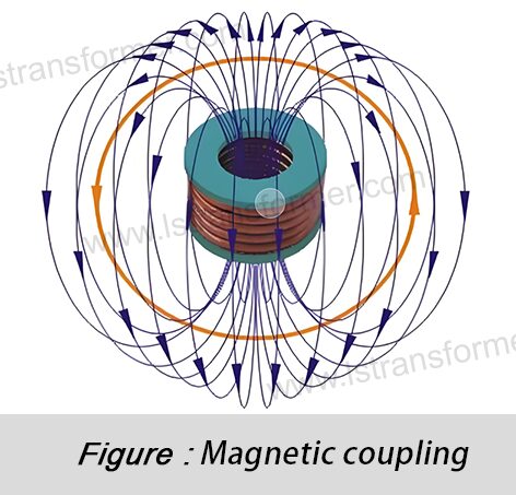
● Inductive Coupling (Magnetic Field Interference)
(1)Cause:A time-varying current (high di/dt, e.g., short-circuit currents or inrush currents) in one conductor generates an alternating magnetic field. When this field passes through a loop formed by a nearby conductor, it induces a voltage (V = -M × di/dt), where M is the mutual inductance.
(2)Impact:Induced voltages superimpose on normal signals, causing relay misoperation, control system failures, or even insulation breakdown.
Interference Type | Coupling Path | Dominant Frequency Range | Main Risks | Sensitive Circuits |
Capacitive (E-field) | Stray capacitance (Cs) | High-frequency (>1 kHz) | Signal distortion, partial discharge, EMI emissions | Voltage measurement, communication, control lines |
Inductive (H-field) | Mutual inductance (M) | Low-to-medium frequency (<1 kHz) | Induced overvoltage, relay misoperation, insulation failure | Current measurement, protection circuits, power lines |
Table 1: Key Interference Types and Characteristics in Multi-Winding Transformer Leads
2. Key Mitigation Strategies: International Best Practices for Interference Suppression
● Optimized Winding Layout and Lead Wire Arrangement (Physical Isolation)
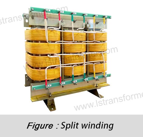
(1)Measures:Follow strict zoning and layering principles. Separate windings of different voltage levels (e.g., HV, MV, LV) or functions (power, control, measurement) spatially. Use perpendicular or crossed lead wire routing to avoid long parallel runs (maximize spacing d).
(2)Physics Behind It:
– Capacitive coupling decreases with distance :
C ∝ ε × A / d
(ε: permittivity, A: overlapping area).
–Mutual inductance (M) depends on loop area (S):
V_ind ∝ M × di/dt ∝ μ₀ × S × N / (2πr) × di/dt
(μ₀: vacuum permeability, N: turns, r: distance).
(3)Standards:IEC 60076-7 (Loading Guide) emphasizes electromagnetic distribution in hotspot control, while IEEE C57.12.00 mandates clearances for safety.
● Electrostatic and Electromagnetic Shielding (Active Isolation)
(1)Measures:
–Electrostatic shielding:Wrap sensitive leads (e.g., measurement/communication wires) in conductive foil/braid (copper/aluminum) and ground at a single point. This creates a Faraday cage, diverting electric fields.
–Electromagnetic shielding:Enclose high-di/dt circuits (e.g., breaker leads) or sensitive paths in high-permeability materials (e.g., mu-metal, amorphous alloys) to confine magnetic fields.
(2)Standards:IEC 62305-4 (lightning protection) provides shielding guidelines for high-voltage systems.
● Impedance Matching and Filtering (Electrical Noise Suppression)
(1)Measures:
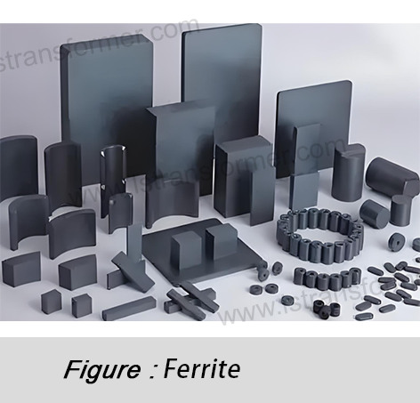
–Ferrite beads:Add ferrite rings to high-frequency noise-prone leads. Their impedance (Z ∝ jωμ) absorbs interference as heat.
–RC/LC filters:Install filters (e.g., low-pass) at sensitive inputs (e.g., measurement windings) to attenuate noise above cutoff frequency (f_c = 1/(2πRC)).
(2)Applications:Effective for switch-mode power supply noise, per IEC 61800-3 (drive system EMC).
● Insulation Material and Structural Design (Dielectric Isolation)
(1)Measures:
–Use high-dielectric-strength materials (e.g., XLPE, silicone rubber, Kapton®) at crossover points.
–Increase creepage/clearance per IEC 60664-1 (insulation coordination).
–For compact designs, use epoxy/polyurethane vacuum casting to eliminate air gaps and improve cooling.
(2)Physics:
–Higher dielectric strength raises partial discharge inception voltage (PDIV).
–Larger creepage distances prevent surface arcing (Paschen’s Law).
(3)Standards:IEC 60076-11 specifies insulation material properties.
Material | Thermal Class (IEC 60085) | Resistivity (Ω·cm) | Dielectric Strength (kV/mm) | Advantages | Applications |
Epoxy (cast) | F (155°C) / H (180°C) | >10¹⁵ | 15–25 | High strength, moisture-resistant | Compact, high-IP-rated transformers |
Nomex® paper | H (180°C) / C (220°C) | >10¹⁴ | 40–60 | Heat/chemical resistant | Traction transformers, high-load |
Silicone rubber | H (180°C) | >10¹⁴ | 20–30 | Flexible, weatherproof | Bushings, outdoor terminals |
Polyimide (Kapton®) | C (220°C) | >10¹⁶ | 200–300 | Ultra-thin, high-temperature | High-frequency/high-temperature windings |
Table 2: Key Properties of Transformer Insulation Materials (per IEC 60216 & UL 1446)
3. Validation: From Design to Testing
International standards require these tests to verify interference mitigation:
(1)Partial Discharge (PD) Test (IEC 60270):Detects micro-discharges in insulation.
(2)Induced Voltage Test (IEC 60076-3):Validates insulation at overvoltage.
(3)Impulse Test (IEC 60076-4):Checks transient overvoltage tolerance.
(4)EMC Tests (IEC 61000-4):Ensures compliance for conducted/radiated emissions.
Simulation tools (e.g., ANSYS Maxwell) optimize designs early, reducing costs.
In Summary
Preventing interference in multi-winding transformer leads requires a holistic approach—combining physical isolation, shielding, filtering, and advanced insulation per IEC/IEEE standards.
Key Stats:
15% of unplanned transformer failures stem from partial discharges (U.S. DOE).
Optimized designs (e.g., shielded/compartmentalized windings) boost MTBF by 40%+ (German VDE).
Contact Us
LuShan, est.1975, is a Chinese professional manufacturer specializing in power transformers and reactors for 50+ years. Leading products aresingle-phase transformer, three-phase isolation transformers,electrical transformer,distribution transformer, step down and step up transformer, low voltage transformer, high voltage transformer, control transformer, toroidal transformer, R-core transformer;DC inductors, ACreactors, filtering reactor, line and load reactor, chokes, filtering reactor, and intermediate,high-frequency products.
Our power transformers and reactors are widely used in 10 application areas: rapid transit, construction machinery, renewable energy, intelligent manufacturing, medical equipment, coal mine explosion prevention , excitation system, vacuum sintering(furnace), central air conditioning.
Know more about power transformer and reactor :www.lstransformer.com.
If you would like to obtain customized solutions for transformers or reactors, please contact us.
WhatsApp:+86 17267488565
Email:marketing@hnlsdz.com

 EN
EN
 FR
FR DE
DE ES
ES


