How to Suppress Reactor Resonance Overvoltage? – Collaborative Design of Damping Resistors and Filters
How to Suppress Reactor Resonance Overvoltage?
– Collaborative Design of Damping Resistors and Filters
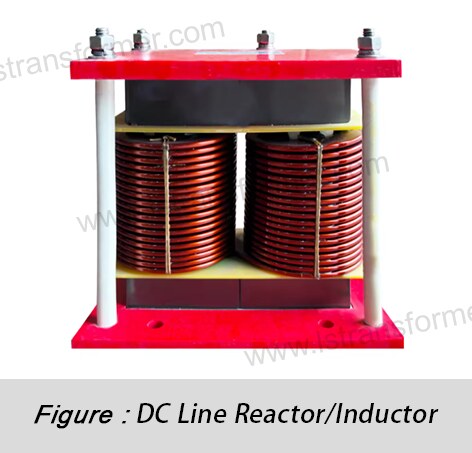
In power system operation, the LC resonance circuit formed by reactors and distributed capacitance can generate dangerous overvoltage phenomena. According to measured data from IEEE Std. C57.21-2021, the peak resonance overvoltage can reach 2-3 times the rated voltage, posing a serious threat to equipment safety. This article delves into the collaborative working principles of damping resistors and active filters, revealing their physical mechanisms and engineering implementation methods for suppressing resonance overvoltage.
Content
1. Generation Mechanism and Hazards of Resonance Overvoltage
● Physical Process of Resonance Formation
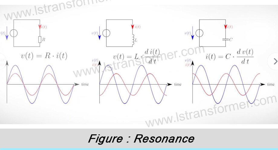
Reactor resonance overvoltage originates from the periodic exchange of electromagnetic energy between inductance (L) and capacitance (C). When the system meets the condition X_L = X_C (i.e., inductive reactance equals capacitive reactance), the system impedance reaches its minimum. The resonance frequency can be precisely calculated as:
fᵣ = 1/(2π√(LC))
This phenomenon is particularly dangerous in systems with harmonic sources. For example, when background harmonics contain frequency components close to fᵣ, tiny harmonic currents can be amplified dozens of times, leading to hazardous voltage spikes.
● Multidimensional Hazards of Overvoltage
The dangers of resonance overvoltage extend beyond instantaneous peak impacts, including cumulative effects from prolonged exposure:
(1)Insulation System Damage Mechanism:Sustained overvoltage intensifies partial discharges within insulation materials, accelerating polymer chain breakage and eventually causing surface flashover or complete breakdown.
(2)Protection System Misoperation:Voltage waveform distortion triggers false signals in overvoltage relays, leading to unnecessary equipment shutdowns during normal operation.
(3)Capacitor Bank Failure Chain Reaction:Overvoltage increases dielectric polarization loss in capacitors, raising temperatures beyond limits and causing permanent damage.
Equipment Type | Lightning Impulse Withstand (kV) | Power Frequency Withstand (kV) | Duration |
35kV Transformer | 170 | 70 | 1 minute |
110kV GIS | 550 | 230 | 1 minute |
10kV Cable | 75 | 25 | 15 minutes |
Table 1: International Standards for Equipment Overvoltage Withstand (IEC 60071-1/IEEE C57.12.00)
2. In-Depth Working Mechanism of Damping Resistors
● Physical Process of Energy Conversion
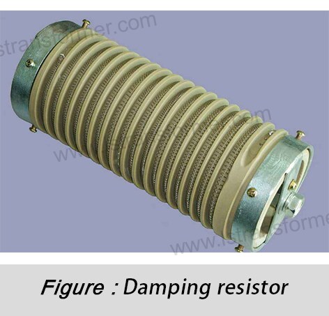
Damping resistors introduce active power loss into the resonance circuit, converting dangerous electromagnetic oscillation energy into heat. This mechanism is described by the second-order differential equation:
L(d²i/dt²) + R(di/dt) + (1/C)i = 0
The resistor R alters the system’s damping characteristics. When the damping coefficient ζ = R/(2√(L/C)) > 1, the system becomes overdamped, completely suppressing oscillations. This process is analogous to adding viscous oil to a swinging pendulum, where friction dissipates kinetic energy to halt motion quickly.
● Core Engineering Design Elements
Optimizing damping resistors requires balancing three key parameters:
(1)Optimal Resistance Range:
– Theoretical best value: R_opt = √(L/C)
– Practical engineering range: (0.3~0.5)X_L @ fᵣ
– Goal: Balance energy dissipation and suppression effectiveness.
(2)Thermal Design Considerations:
Power calculation:
P = V_peak² / R
Where V_peak is the estimated overvoltage peak and t_res is the resonance duration. A 30% margin is recommended to account for system parameter fluctuations.
(3)Dynamic Response Solutions:
Modern systems use Thyristor-Controlled Resistive Damping (TCRD), which detects resonance within 10ms and deploys precise resistance, disconnecting during normal operation to avoid losses.
3. Collaborative Mechanism of Active Filters
● Physical Implementation of Harmonic Elimination
Active Power Filters (APF) generate inverse harmonic currents in real-time for compensation. Core technologies include instantaneous reactive power theory and coordinate transformation:
(1)Park Transform converts three-phase time-varying signals into DC components in a rotating coordinate system.
(2)In the dq coordinate system, harmonics appear as AC components, separable via low-pass filtering.
(3)The controller generates compensation commands, which are inverted to drive IGBTs and produce counter-phase currents.
● Synergistic Effects with Damping Resistors
The two systems form a multi-level protection scheme:
(1)Primary Layer (Active Defense):APF eliminates harmonic sources within 100μs, preventing resonance excitation.
(2)Secondary Layer (Passive Protection):If APF fails or encounters unanticipated harmonics, damping resistors provide an energy dissipation path.
(3)Dynamic Coordination:The control system intelligently switches modes based on dv/dt rate changes.
Performance Metric | No Suppression | Damping Resistor Only | APF Only | Collaborative Solution |
Overvoltage Multiple (pu) | 1.82 | 1.45 | 1.32 | 1.19 |
Attenuation Time (ms) | Sustained Oscillation | 85 | 15 | 8 |
Annual Failure Count | 17 | 5 | 3 | 0 |
Additional Losses (kW) | 0 | 35 | 2.5 | 3.1 |
Table 2: Performance Comparison of Collaborative Solution in a 115kV Substation
Suppressing reactor resonance overvoltage requires a systematic, multi-pronged engineering approach. By understanding the physical principles of resonance and employing damping resistors + active filters, a dual-layer protection system ("active elimination + passive protection") achieves optimal suppression. Implementation should follow the "Precise Measurement → Digital Modeling → Optimized Design → Field Validation" workflow, using internationally certified equipment with adequate capacity margins.
Modern suppression technologies achieve >95% overvoltage reduction, and advancements like wideband damping, AI predictive control, and solid-state modules continue to enhance power system safety. Ultimately, an effective resonance suppression scheme should function like precision clockwork, harmonizing safety and efficiency for long-term equipment reliability.
Contact Us
LuShan, est.1975, is a Chinese professional manufacturer specializing in power transformers and reactors for 50+ years. Leading products aresingle-phase transformer, three-phase isolation transformers,electrical transformer,distribution transformer, step down and step up transformer, low voltage transformer, high voltage transformer, control transformer, toroidal transformer, R-core transformer;DC inductors, AC reactors, filtering reactor, line and load reactor, chokes, filtering reactor, and intermediate,high-frequency products.
Our power transformers and reactors are widely used in 10 application areas: rapid transit, construction machinery, renewable energy, intelligent manufacturing, medical equipment, coal mine explosion prevention , excitation system, vacuum sintering(furnace), central air conditioning.
Know more about power transformer and reactor :www.lstransformer.com.
If you would like to obtain customized solutions for transformers or reactors, please contact us.
WhatsApp:+86 13787095096
Email:marketing@hnlsdz.com

 EN
EN
 FR
FR DE
DE ES
ES


