How to Address Excessive Temperature Rise? —A Triple Approach: Radiator Selection, Airflow Optimization, and Hotspot Suppression
How to Address Excessive Temperature Rise?
—A Triple Approach: Radiator Selection, Airflow Optimization, and Hotspot Suppression
Excessive temperature rise in transformers is a critical issue faced by many power engineers. High temperatures not only accelerate the aging of insulation materials, significantly shortening equipment lifespan, but can also lead to catastrophic failures such as insulation breakdowns, fires, or even explosions. This article delves into three core strategies: scientific radiator selection, optimized airflow system design, and precise hotspot temperature suppression, providing a systematic solution to tackle temperature rise challenges and ensure safe, efficient, and long-lasting transformer operation.
1.Scientific Radiator Selection—The Foundation of Cooling Capacity
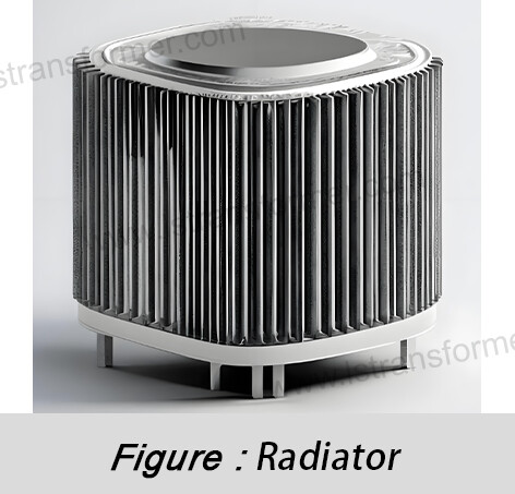
Radiators are the primary channel for dissipating transformer heat into the environment. Their working principle involves increasing surface area to enhance heat dissipation. As transformer oil flows through the radiator, heat transfers from the metal surface to the air. Radiator selection directly determines the upper limit of cooling capacity.
● Core Principle: Precise Matching of Cooling Capacity and Heat Generation
The foremost task is ensuring the radiator’s rated cooling power (P_radiator) meets or exceeds the transformer’s estimated maximum total losses (P_total_loss), with a reasonable design margin (typically 15%–25%). P_total_loss includes no-load losses (core losses, P_no_load) and load losses (winding copper losses, P_load).
Calculation example:
P_total_loss = P_no_load + P_load × (Loading Factor)²
For a transformer with P_no_load = 50 kW, P_load = 200 kW @ 100% load, and a maximum operating load of 90%:
P_total_loss = 50 + 200 × (0.9)² = 50 + 162 = 212 kW
The radiator’s cooling capacity must satisfy:
P_radiator ≥ 212 × 1.2 ≈ 254.4 kW (20% margin)
● Type Selection: Context Matters
Common radiator types and their applications:
Radiator Type | Cooling Method | Typical Applications | Cooling Capacity | Complexity/Cost |
Plate Radiator | Natural Oil Circulation (ONAN) | Small distribution transformers, indoor stations | Low, relies on natural convection | Low/Low |
Flat Tube Radiator | Natural Oil Circulation (ONAN) | Small/medium oil-immersed transformers | Moderate, larger surface area | Medium/Medium |
Finned Tube Radiator | Natural Oil Circulation (ONAN) | Space-constrained medium transformers | High (compact efficiency) | Medium/Medium-High |
Forced Oil Radiator | Forced Oil Air Cooling (OFAF) | Large power transformers, high-load/high-temp | High, fan-forced cooling | High/High |
Directed Oil Flow Radiator | Directed Oil Air Cooling (ODAF) | Extra-large transformers (>100MVA), strict hotspot control | Highest, targeted oil flow | Very High/Very High |
● Performance Deep Dive: Beyond Surface Area
(1)Fin Efficiency (η_f):Fin tips are cooler than roots; effective cooling area is reduced. η_f depends on material thermal conductivity (λ), thickness (δ), height (H), and surface heat transfer coefficient (h):
η_f ≈ tanh(mH) / (mH)
High λ (e.g., aluminum alloy >200 W/mK vs. carbon steel ~50 W/mK) and optimized δ/H improve η_f.
(2)Oil Flow Resistance & Pump Loss:In forced oil systems (OFAF), radiator design affects pump power. Larger flow paths or smoother walls reduce resistance (ΔP ∝ velocity²), minimizing parasitic losses.
(3)Environmental Adaptability:High-pollution areas (dust, debris) require wider fin spacing (>6mm); coastal regions demand corrosion-resistant coatings/alloys.
2.Airflow Optimization—Enhancing Air-Side Heat Exchange
Even with robust radiators, poor airflow design can severely hinder cooling.
● Airflow Principles: Minimize Resistance, Maximize Flow
Key goals: Ensure low-resistance paths, uniform airflow across fins, and no hot air recirculation.
● Optimization Measures:
(1)Adequate Inlet Area & Clean Air:Inlet area (A_inlet) must satisfy: A_inlet ≥ Q_air / V_inlet, where Q_air is total airflow (calculated from cooling needs) and V_inlet is recommended inlet velocity (2–4 m/s). Use easy-to-maintain filters.
(2)Eliminate Short-Circuiting: Separate hot/cold airflows strictly:
–Physical Barriers:Install baffles between radiators or walls.
–Pressure Zones:Use fans and cabinet design to create clear negative (inlet)/positive (outlet) pressure zones.
–Clearance:Maintain >1.5× outlet diameter from obstacles to prevent hot air re-entry.
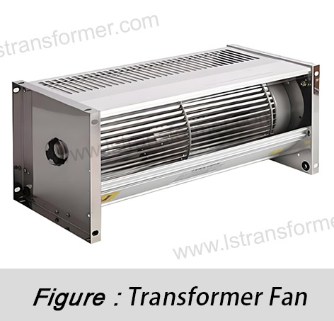
(3)Fan Selection & Layout (OFAF/ODAF):
–Match fan performance curves to system resistance.
–Uniform airflow:Symmetrical fan placement or diffusers for wide radiators.
–Redundancy & VFD:N+1 redundancy or variable-speed fans reduce energy/noise at low loads.
(4)Chimney Effect:For natural cooling (ONAN), vertical exhaust ducts enhance thermal buoyancy.
3.Hotspot Suppression—Targeting Weak Points
Winding hotspots drive insulation aging (per IEC/IEEE limits), often 15–40°C hotter than top oil temperature.
● Hotspot Causes:
(1)Eddy Current Concentration:High local losses in winding ends, transpositions, or leads due to magnetic field distortion.
(2)Uneven Oil Flow:Poorly designed/clogged oil channels reduce cooling.
(3)Structural Losses:Stray-induced eddy currents in clamps/tank walls heat nearby oil.
● Core Technology: Directed Oil Flow (ODAF)
ODAF directs oil to critical areas via pumps, insulated ducts, and nozzles, offering:
(1)Boundary Layer Disruption:High-speed oil jets enhance heat transfer (h ∝ velocity^0.6–0.8).
(2)Dead Zone Elimination:Ensures full oil coverage in complex winding regions.
(3)Lower Average Oil Temp:Improves baseline cooling for hotspots
Result:ODAF reduces hotspots by 10–25°C vs.
● Supplementary Measures:
(1)Electromagnetic Shielding:Non-magnetic steel (e.g., stainless) or copper/aluminum shields near high-leakage zones reduce tank wall eddy currents.
(2)Advanced Coatings:High-λ nano-coatings (e.g., boron nitride, graphene) on windings/insulation improve heat conduction (emerging technology).
Hotspot Location | Cause | Solution |
Mid-upper winding height | High losses, low oil flow | ODAF + optimized axial oil channels |
Winding ends (especially HV) | Leakage field concentration | ODAF + electromagnetic shielding |
Lead connections/tap changers | High current density, poor cooling | Local oil jets + larger conductors |
Core-adjacent winding zones | Combined main/stray fields | Shielding + optimized oil paths |
In Summary
Addressing transformer temperature rise requires a holistic approach: proper radiator selection, optimized airflow, and targeted hotspot suppression. For tailored solutions, contact our technical team for expert cooling optimization advice.
Contact Us
LuShan, est.1975, is a Chinese professional manufacturer specializing in power transformers and reactors for 50+ years. Leading products aresingle-phase transformer, three-phase isolation transformers,electrical transformer,distribution transformer, step down and step up transformer, low voltage transformer, high voltage transformer, control transformer, toroidal transformer, R-core transformer;DC inductors, AC reactors, filtering reactor, line and load reactor, chokes, filtering reactor, and intermediate,high-frequency products.
Our power transformers and reactors are widely used in 10 application areas: rapid transit, construction machinery, renewable energy, intelligent manufacturing, medical equipment, coal mine explosion prevention , excitation system, vacuum sintering(furnace), central air conditioning.
Know more about power transformer and reactor :www.lstransformer.com.
If you would like to obtain customized solutions for transformers or reactors, please contact us.
WhatsApp:+86 13787095096
Email:marketing@hnlsdz.com

 EN
EN
 FR
FR DE
DE ES
ES


