 EN
EN
 FR
FR DE
DE ES
ES
How to Mitigate Skin Effect in High-Frequency Inductors? — Analysis of Litz Wire Braiding and Multi-Layer Winding Design
How to Mitigate Skin Effect in High-Frequency Inductors?
— Analysis of Litz Wire Braiding and Multi-Layer Winding Design
In high-frequency power electronic systems such as switching power supplies, new energy inverters, and variable frequency drives, high-frequency inductors are the core magnetic components enabling efficient energy conversion. However, as operating frequencies rise to the kHz or even MHz range, a persistent physical phenomenon—skin effect—drastically increases winding AC losses, leading to excessive device temperature rise, reduced efficiency, and even magnetic core saturation failure. Statistics show that at 100kHz, the skin effect can cause the effective AC resistance of conductors to be more than 5 times the DC resistance, with losses accounting for over 30% of the total system losses.
How to overcome the skin effect? This article will deeply analyze two core solutions: precision braiding of Litz wire and multi-layer parallel winding design, revealing the underlying electromagnetic principles and engineering practices.
Content
1. Skin Effect: The "Invisible Killer" of High-Frequency Losses
● Problem (Cause):

When an AC current passes through a conductor, the changing current generates a varying magnetic field inside the conductor, which in turn induces eddy currents. According to Lenz’s Law, the direction of eddy currents always opposes the change in the original current, resulting in uneven current density distribution across the conductor cross-section: current is "pushed" to the conductor surface, while the current density in the central region decreases significantly. This phenomenon is the skin effect.
● Skin Depth (δ):
Skin depth defines the depth at which the current density drops to 37% of the surface value. The is:
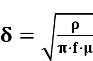
Where:
 : Skin depth (m)
 : Conductor resistivity (Ω·m), ~1.68×10⁻⁸ for copper
 : Operating frequency (Hz)
 : Conductor permeability (H/m),
 =4π×10⁻⁷ for copper
Example:
For copper wire at 100kHz,δ≈0.21mm; at 1MHz,δ≈0.066mm.
This means:
If the wire diameter > 2δ (0.42mm at 100kHz), the central region utilization is extremely low, and the equivalent AC resistance ( ) surges.
The (AC to DC resistance ratio) of traditional solid round wires rises sharply at high frequencies, causing copper losses dominated by eddy current losses.
● Severe Consequences (Effect):
(1)Efficiency Plummets:Losses ∝ , temperature rise ΔT ∝ losses.
(2)Local Overheating:The temperature difference between the inside and outside of the wire can exceed 30°C, accelerating insulation aging.
(3)Design Bottlenecks:To control temperature rise, current density must be reduced, leading to larger magnetic component.The skin effect is essentially the "expulsion effect" of the electromagnetic field on the conductor. The key to breaking through it lies in reconstructing the electromagnetic field distribution inside the conductor.
2. Litz Wire: Reconstructing Electromagnetic Fields by Trading Space for Efficiency

● Solution Principle (Measure):
Litz wire is composed of hundreds to thousands of mutually insulated ultra-fine wires (diameter < 2δ) twisted and braided according to specific rules. Its core advantages in mitigating the skin effect lie in two points:
● Filament Segmentation:
Divide a large cross-section conductor into N independently insulated filaments (diameterd≤δ). Each filament’s cross-section is smaller than the skin depth, allowing current to distribute uniformly across its entire cross-section, avoiding internal eddy current losses. At this point, the of a single filament ≈
 .
.
●Periodic Transposition Braiding:
During twisting, each filament periodically exchanges spatial positions along the axis (e.g., braiding angle θ=15°~25°). This ensures that each filament is uniformly exposed to high/low magnetic field regions along the length, eliminating circulating current losses (proximity effect) caused by fixed positions.
Performance Improvement (Effect):
(1)Rac/Rdc Approaches 1:Under ideal braiding, the AC resistance of Litz wire in the target frequency band ≈ DC resistance.
(2)Losses Reduced by 40~70%:Compared to solid wires of the same cross-sectional area, high-frequency eddy current losses are significantly reduced.
(3)Uniform Temperature Distribution:The temperature difference between filaments is <5°C, extending insulation life.
Key Parameters for Litz Wire Selection
Parameter | Optimization Goal | Engineering Constraints |
Single Filament Diameter (d) | d≤δ (skin depth at target frequency) | Too fine increases processing difficulty/cost |
Stranding Pitch (p) | p≤10d (suppress circulating current effect) | Too small reduces flexibility |
Braiding Layers | ≥3 layers (ensure sufficient transposition) | More layers increase cost |
Insulation Thickness | 2~5μm (polyurethane/AIW) | Too thick reduces fill factor |
Example: For a 500kHz/50A inductor, → select Litz wire with
 (≈2000 strands) and braiding angle θ=20°. The measured
 (theoretical value for solid wire >5).
3. Multi-Layer Parallel Winding: Active Regulation of Magnetic Field Interference
● Solution Principle (Measure):
When Litz wire is too costly or space is limited (e.g., planar transformers), multi-layer parallel winding becomes an optimized solution. It reduces losses by precisely controlling the thickness and spacing of each layer and utilizing the phase cancellation effect of eddy currents in adjacent layers:
(1)Layer Thickness ≤ δ Principle:
Control the thickness of each layer conductor within δ to ensure uniform current distribution within the layer (similar to the filamentation of Litz wire).
(2)Reverse Current Interference:
Pass same-direction current through adjacent layers (both input or output). According to Ampère’s Circuital Law, the magnetic fields between layers are in opposite directions, inducing eddy currents in opposite directions, which partially cancel each other (see figure below):
– 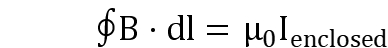
– The reverse magnetic fields between adjacent layers weaken the net magnetic field strength, reducing eddy current amplitude.
● Key Winding Structure Optimizations:
(1)Layer Spacing Optimization:Too small increases capacitance, too large weakens the cancellation effect → recommended spacing ≈ layer thickness.
(2)End Cross Transposition:Cross at layer connection points to balance impedance between layers.
(3)Magnetic Core Window Utilization: Prioritize wide and flat windows to increase the number of parallel layers.
● Performance Improvement (Effect):
(1)Eddy Current Losses Reduced by 30~50%: Compared to unoptimized multi-layer windings.
(2)Compatible with PCB Process: Suitable for mass production of planar magnetic components.
(3)Cost Significantly Lower Than Litz Wire: Saves 30%+ conductor cost.
4. Technical Scheme Comparison and Selection Guide
Scheme | Litz Wire | Multi-Layer Parallel Winding |
Core Principle | Filament insulation segmentation + spatial transposition | Layer thickness control + reverse eddy current cancellation |
Optimal Frequency Band | 10kHz ~ 2MHz | 50kHz ~ 500kHz |
Loss Suppression Rate | 40~70% (vs. solid wire) | 30~50% (vs. unoptimized winding) |
Process Complexity | High (precision twisting/insulation) | Medium (requires interlayer insulation and end processing) |
Cost Factor | High (materials and manufacturing account for 30~50%) | Medium (equivalent to standard windings) |
Applicable Scenarios | High current/high frequency/extreme efficiency requirements | Planar magnetic components/medium frequency/cost-sensitive designs |
Standard References | IEC 60317-0-1 (general specification for Litz wire) | IPC-2221 (PCB winding spacing design) |
Note: For ultra-high frequencies >1MHz, further optimization with foil windings + nanocrystalline cores is required (δ<0.05mm).
In Summary
The skin effect in high-frequency inductors is essentially energy dissipation caused by imbalanced electromagnetic field distribution. Litz wire reconstructs the current path through micro-filament segmentation and spatial transposition, achieving optimal loss suppression in the 10kHz~2MHz band; multi-layer parallel winding provides a cost-effective solution for 50kHz~500kHz planar magnetic components by leveraging the interference effect of eddy currents in adjacent layers. Both solutions require precise adherence to the physical constraints of skin depth (δ) and compliance with international standards such as IEC/IPC for process control.
The choice of scheme depends on the three-dimensional trade-off between frequency, current, cost, and space—only by deeply understanding the mutual exclusion规律between electromagnetic fields and conductors can we win the high-frequency battle in the balance between efficiency and density. The pain of conductors is solved by fields; the peak of energy efficiency is achieved by design.
Contact Us
LuShan, est.1975, is a Chinese professional manufacturer specializing in power transformers and reactors for50+ years. Leading products are single-phase transformer, three-phase isolation transformers,electrical transformer,distribution transformer, step down and step up transformer, low voltage transformer, high voltage transformer, control transformer, toroidal transformer, R-core transformer;DC inductors, AC reactors, filtering reactor, line and load reactor, chokes, filtering reactor, and intermediate,high-frequency products.
Our power transformers and reactors are widely used in 10 application areas: rapid transit, construction machinery, renewable energy, intelligent manufacturing, medical equipment, coal mine explosion prevention , excitation system, vacuum sintering(furnace), central air conditioning.
Know more about power transformer and reactor :www.lstransformer.com.
If you would like to obtain customized solutions for transformers or reactors, please contact us.
WhatsApp:+86 17267488565
Email:[email protected]