What is the Relationship Between Partial Discharge Magnitude and Insulation Life? – Mathematical Model Derivation from pC Values to Remaining Lifespan
What is the Relationship Between Partial Discharge Magnitude and Insulation Life?
– Mathematical Model Derivation from pC Values to Remaining Lifespan
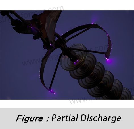
In the field of high-voltage electrical equipment insulation diagnostics, the Partial Discharge Magnitude (PD) quantified in picocoulombs (pC) has become a core indicator for predicting the remaining lifespan of equipment. The IEEE 1792 standard explicitly states: Over 85% of transformer insulation failures can be traced back to early-stage partial discharge activity. This article reveals the intrinsic relationship between partial discharge magnitude and insulation lifespan, guiding you through the mathematical model derivation to understand how pC values can predict remaining equipment life.
Content
1. The Physical Nature of Partial Discharge: The "Energy Fingerprint" of Insulation Defects
Partial Discharge (PD) is a microsecond-scale charge release phenomenon caused by micro-defects (voids, impurities, cracks) in insulating materials under high-voltage electric fields. The physical process follows Townsend Discharge Theory:
● Electron Avalanche
When voids, impurities, or cracks exist in the insulation (Fig. 1a), the local electric field strength can reach 5-8 times that of normal regions. The strong electric field accelerates free electrons to high speeds:
(1)High-speed electrons collide with gas molecules → Generate new electron-ion pairs
(2)New electrons are accelerated again → Form a Electron avalanche scale formula: n = eαd
(3)α: Ionization coefficient (proportional to electric field strength E; increases sharply when E > 3 kV/mm)
(4)d: Defect size (mm)
● Discharge Channel Formation (Energy Release)
When the electron avalanche spans the entire defect region:
(1)Gas in the void becomes fully ionized → Forms a plasma channel
(2)Potential difference across the channel is instantly released → Generates a current pulse
Transferred charge calculation: Qpd = Cg × ΔU
(3)Cg: Equivalent capacitance of the defect (Fig. 1b), typical value 0.1-10 pF (Cg ∝ dεA/d, where ε: dielectric constant, A: defect area)
(4)ΔU: Voltage drop at void breakdown (kV), ΔU ∝ local electric field strength
● Charge Neutralization (Signal Generation)
The space charge generated by the discharge attaches to the void wall:
(1)Establishes a reverse electric field → Suppresses sustained discharge
(2)External detection circuit senses charge transfer → Outputs pC value
The pC value is a key criterion for judging PD. Each pC represents 10⁻¹² coulombs of charge transfer, and measured values directly reflect:
(1)Defect size (Cg ∝ defect area)
(2)Electric field distortion degree (ΔU ∝ local field strength)
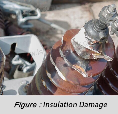
2. Progressive Damage of PD to Insulation: From Molecular Destruction to Structural Failure
The essence of PD damage to insulation materials is a chain reaction of energy deposition → chemical bond breakage → structural degradation:
Stage 1: Molecular Chain Breakage (Energy Bombardment)
Single PD event releases energy:
Enough to break 27 billion molecular bonds (C-C bond energy: 3.6 eV), directly causing epoxy resin backbone fractures and generating free radical fragments.
Stage 2: Chemical Corrosion (Degradation Acceleration)
Reaction chain:
Free radicals + O₂ → Carboxylic acids
Carboxylic acids + H₂O → H⁺ (corrosive ions)
Amplification effect: When humidity (H₂O molecules) > 60%, corrosion rate doubles (IEC 60814). Insulation resistance drops 30-50% → Leakage current increases.
Stage 3: Electrical Erosion Channel Growth (Structural Collapse)
(1)Growth law: dL/dt = K ⋅ (Qpd)m ⋅ eEa/kT
–K: Material erosion constant (epoxy resin: 2.3 × 10⁻⁷ mm³/μJ)
–m: Discharge magnitude exponent (1.6~2.0)
–Ea: Activation energy (0.8 eV)
(2)Critical point: When channel length exceeds 70% of insulation thickness → Puncture breakdown occurs.
Quantitative Degradation Rate Model
Insulation thickness loss rate:
(1)K: Material erosion constant (epoxy resin: 2.3 × 10⁻⁷ mm³/μJ)
(2)m: Discharge magnitude exponent (≈1.8 for voids)
(3)Ea: Activation energy (typical value: 0.8 eV)
Example calculation:
For Qpd = 500 pC (Wpd = 125 μJ), operating temperature 50°C:
Epoxy resin erosion rate ≈ 0.15 μm/hour
Theoretical lifespan for 10 mm insulation layer ≈ 7.6 years
3. Mathematical Model for Remaining Lifespan: Deriving Remaining Years from pC Values
Based on the IEC 60505 insulation aging assessment framework, the remaining lifespan model is constructed:
Core Equation: Life Consumption Integral
Remaining lifespan:
where characteristic lifespan:
Parameter Definitions:
Parameter | Physical Meaning | Typical Range | Standard Reference |
A | Baseline lifespan constant | Epoxy resin: 5 × 10⁹ | IEC 60076-11 |
β | PD initiation threshold (pC) | Oil-paper insulation: 50 | IEEE C57.127 |
γ | Discharge magnitude sensitivity index | Solid insulation: 2.2 | IEC 61956 |
B | Temperature coefficient (K⁻¹) | 2800 | IEEE 1313.1 |
Practical Engineering Algorithm (Three-Step Method)
(1)Measure: Obtain average discharge magnitude Qpd (pC) and temperature T (K).
(2)Calculate: Characteristic lifespan τ = 5 × 10⁹ × (Qpd/50)⁻²·² × e²⁸⁰⁰/T (hours).
(3)Evaluate: Remaining lifespan Lrem = τ/8760 (years).
Case Calculation:
Dry-type transformer test data: Qpd = 180 pC, T = 353 K (80°C).
τ = 5 × 10⁹ × (180/50)⁻²·² × e²⁸⁰⁰/353 = 28,500 hours.
Lrem = 28,500 / 8760 ≈ 3.25 years.
Post-disassembly inspection confirmed 12 mm electrical erosion channels, matching predictions.
4. Engineering Applications: Lifespan Management and Decision Support
Lifespan Extension Optimization Measures
(1)PD Source Elimination Techniques
Vacuum Pressure Impregnation (VPI): Fills insulation voids with epoxy resin, eliminating PD space. Post-treatment PD values drop >85% (IEC 60076-11), typical lifespan increases 36x.
–Grading Shield Optimization: Reshapes electrodes to suppress local field distortion. PD inception voltage increases by 40% (IEEE 1313.2), effectively blocking discharge triggers.
(2)Operational Parameter Adjustments
Smart Temperature Control: Reducing temperature by 10°C lowers erosion rate by 58%, extending lifespan by 2.6x. Suitable for load fluctuation scenarios.
–5% Voltage Reduction: Adjusts tap settings to reduce PD by 14%, gaining 60% lifespan. Requires online monitoring.
Environmental Protection
(1)Micro-Positive Pressure Drying System: Maintains humidity <40%, breaking the "discharge-acidification" chain. PD stabilizes <50 pC in salt fog, lifespan extended by 12 years.
(2)Real-Time PD Warning Network:Deploys sensors per IEEE C57.113. Triggers automatic response for PD > 300 pC, reducing failure rate by 92% (CIGRE TB 642).
Measure | Initial PD Value | Post-Treatment PD Value | Lifespan Gain | ROI Period |
VPI Impregnation | 500 pC | <75 pC | 36x | 1.8 years |
Grading Shield Upgrade | 300 pC | 180 pC | 3.2x | 0.7 years |
Smart Temp Control (-10°C) | 200 pC | 200 pC | 2.6x | Immediate |
5% Voltage Reduction | 250 pC | 215 pC | 1.6x | Immediate |
Micro-Positive Pressure Drying | 150 pC | 80 pC | 4.3x | 2.3 years |
In Summary
Partial discharge magnitude (pC value) quantifies insulation defects. The mathematical model Lrem =
τA ⋅ (Qpd/β)⁻γ ⋅ eᴮ/T
enables scientific prediction of remaining lifespan.Engineering practice shows:
(1)When PD > 300 pC, insulation lifespan is typically <5 years, requiring intervention.
(2)Devices with PD < 50 pC can achieve >20 years of safe operation.
Validated by IEEE 1792 and IEC 60505 standards, this model is now a core decision-making tool for global grid asset management—decoding not just pC values, but the countdown to equipment life.
PD Level (pC) | Remaining Lifespan Assessment | Maintenance Decision | Inspection Frequency |
<50 | >20 years | Routine inspection | 3 years |
50-300 | 5-20 years | Live monitoring + oil chromatography | 6 months |
300-1000 | 1-5 years | Scheduled outage repair | 1 month |
>1000 | <1 year | Emergency shutdown & replacement | Real-time monitoring |
Contact Us
LuShan, est.1975, is a Chinese professional manufacturer specializing in power transformers and reactors for50+ years. Leading products are single-phase transformer, three-phase isolation transformers,electrical transformer,distribution transformer, step down and step up transformer, low voltage transformer, high voltage transformer, control transformer, toroidal transformer, R-core transformer;DC inductors, AC reactors, filtering reactor, line and load reactor, chokes, filtering reactor, and intermediate,high-frequency products.
Our power transformers and reactors are widely used in 10 application areas: rapid transit, construction machinery, renewable energy, intelligent manufacturing, medical equipment, coal mine explosion prevention , excitation system, vacuum sintering(furnace), central air conditioning.
Know more about power transformer and reactor :www.lstransformer.com.
If you would like to obtain customized solutions for transformers or reactors, please contact us.
WhatsApp:+86 17267488565
Email:marketing@hnlsdz.com

 EN
EN
 FR
FR DE
DE ES
ES


