Solutions
Revealing the Impedance-Frequency Characteristics of Reactors – From Power Frequency to High Frequency
Product Profile:
Product Applications
Revealing the Impedance-Frequency Characteristics of Reactors
– From Power Frequency to High Frequency
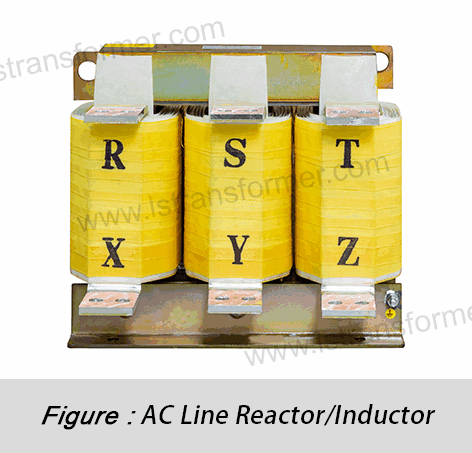
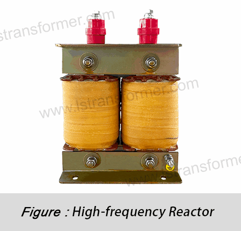
In power systems and electronic devices, reactors play a critical role. But did you know that the same reactor exhibits entirely different impedance characteristics at different frequencies? This frequency dependency directly impacts reactor performance in various applications. This article delves into the impedance variation patterns of reactors from power frequency (50/60Hz) to high frequency (kHz range), uncovering the underlying physics and providing practical selection guidelines. Whether you're a power engineer, electronic designer, or technician in related fields, understanding these characteristics will help you choose and use reactors more effectively.
Content
1. Reactor Impedance Basics: The Inductive-Dominant Nature
The core function of a reactor is to provide controllable inductance (L). At low frequencies, its impedance (Z) is primarily determined by inductive reactance (X_L). Grasping this relationship is key to mastering frequency-dependent behavior.
● Core Formula & Physical Basis:
X_L = 2πfL
● Cause-and-Effect Analysis:
(1) Role of Frequency (f): Higher frequency (↑f) means faster current direction changes (↑di/dt), leading to stronger back EMF and greater opposition to current changes. Thus, X_L increases linearly with frequency—a fundamental property of inductors.
(2) Role of Inductance (L): A higher inductance (↑L) generates stronger back EMF for the same di/dt, increasing X_L linearly.
● Conclusion:For ideal inductors or at low frequencies, reactor impedance ≈ X_L (= 2πfL), rising linearly with frequency. This is the foundation for understanding reactor frequency characteristics.
2. Power Frequency Range (50/60Hz): Stable Impedance for Reactive Compensation & Current Limiting
Power frequency (50Hz in IEC regions like Europe/China; 60Hz in IEEE regions like North America/Japan) is the backbone of power systems. Here, reactors are designed for stable, high inductive reactance.
● Impedance Behavior:
(1)Large and stable impedance.
(2)Resistive component is negligible.
● Key Applications & Principles:
Reactive Power Compensation:
(1)Issue:Capacitor banks compensate for reactive power (e.g., from motors/transformers), improving power factor. However, switching surges or voltage spikes can damage capacitors.
(2)Solution: Series reactors limit surge currents. At power frequency, X_L is high; for high-frequency surges, X_L increases further, suppressing harmful currents.
● Short-Circuit Current Limiting:
(1)Issue:Reactors at critical nodes (e.g., generator outlets) limit fault currents.
(2)Effect:Even during faults, the current’s fundamental frequency remains 50/60Hz. Reactors add impedance, reducing fault current magnitude.
● Summary:At power frequency, reactors rely on stable X_L for surge suppression and fault current limiting. Design focuses on precise inductance and low losses.
3. Mid-Frequency Range (Harmonics, 100Hz–kHz): Resonance Risks & Filtering
Harmonics (integer multiples of power frequency, e.g., 3rd/150Hz, 5th/250Hz) arise from nonlinear loads (e.g., inverters, rectifiers).
● Impedance Changes:
(1)X_L increases linearly with frequency (e.g., 5th harmonic X_L = 5× power frequency X_L).
(2)Winding capacitance (C_w) effects emerge, altering the equivalent circuit (L, R, C_w).
● Critical Risk: Resonance
(1)Condition: X_L = X_C at a harmonic frequency→series/parallel resonance.
(2)Formula: Resonant frequency f_r = 1 / (2π√(LC)).
(3)Consequences: Amplified harmonic currents/voltages, equipment damage, or grid distortion.
(4)Solution: Tuned reactors (LC filters) absorb specific harmonics while avoiding resonance.
● Detuning Consideration:
Designs account for component aging/frequency drift, ensuring±5–10% tolerance (per IEC/IEEE standards).
4. High-Frequency Range (>1kHz): Impedance Drop & Loss Surge
Beyond 1kHz (e.g., switch-mode power supplies, EMI filters), reactor behavior diverges:
● Key Changes:
(1)Impedance peaks then declines (due to self-resonance frequency, SRF).
(2)Losses (core/copper) skyrocket, raising temperatures.
(3)Phase angle shifts from +90°(inductive) to 0°(resistive) or negative (capacitive).
● Root Causes:
Dominant Winding Capacitance (C_w):
(1)At high frequencies, C_w provides a low-impedance bypass path.
(2)Self-Resonance Frequency (SRF): f_srf = 1 / (2π√(LC_w)), where |Z| peaks. Beyond SRF, impedance drops.
High-Frequency Losses:
(1)Core Losses: Eddy currents (∝f²) and hysteresis (∝f) dominate. Mitigated via thin laminations or ferrites.
(2)Copper Losses: Skin/proximity effects (∝ √f) increase AC resistance. Litz wire or foil windings reduce losses.
Loss Type | Mechanism | Frequency Dependence | Mitigation |
Eddy Current | Magnetic field-induced circulating currents | ∝ f² | Thin laminations, powdered cores |
Skin Effect | Current crowds near conductor surface | R_AC ∝ √f | Litz wire, foil windings |
Proximity Effect | Adjacent conductor interactions | R_AC ∝ f (severe cases) | Optimized winding spacing |
Hysteresis | Magnetic domain friction | ∝ f | Soft magnetic materials (low coercivity) |
● Summary: High-frequency challenges include SRF limitations and losses. Design focuses on SRF optimization, material selection (ferrites, powdered cores), and thermal management.
5. Frequency Range Summary & Selection Guide
Frequency | Dominant Trait | Impedance Formula | Key Parameters | Applications |
Power (50/60Hz) | Stable X_L | Z ≈ 2πfL | L accuracy, current rating | Current limiting, reactive compensation |
Harmonics (100Hz–kHz) | X_L rise, resonance risks | Z ≈ √(R² + (X_L - X_C)²) | L, C_w, tuning precision | Harmonic filters |
High (>1kHz) | SRF-driven Z drop | f < SRF: Z↑; f > SRF: Z↓ | SRF, core/copper losses | Switch-mode PSUs, EMI filters |
In Summary
Reactor impedance exhibits three distinct frequency zones. For power applications, prioritize X_L stability; for harmonics, focus on tuning accuracy; for high frequencies, ensure SRF and thermal resilience. Aligning these traits with application needs ensures optimal reactor selection.
Contact Us
LuShan, est.1975, is a Chinese professional manufacturer specializing in power transformers and reactors for50+ years. Leading products are single-phase transformer, three-phase isolation transformers,electrical transformer,distribution transformer, step down and step up transformer, low voltage transformer, high voltage transformer, control transformer, toroidal transformer, R-core transformer;DC inductors, AC reactors, filtering reactor, line and load reactor, chokes, filtering reactor, and intermediate,high-frequency products.
Our power transformers and reactors are widely used in 10 application areas: rapid transit, construction machinery, renewable energy, intelligent manufacturing, medical equipment, coal mine explosion prevention , excitation system, vacuum sintering(furnace), central air conditioning.
Know more about power transformer and reactor:www.lstransformer.com.
If you would like to obtain customized solutions for transformers or reactors, please contact us.
WhatsApp:+86 13787095096
Email:marketing@hnlsdz.com
Get In Touch
We'll get back to you as soon as possible

 EN
EN
 FR
FR DE
DE ES
ES


