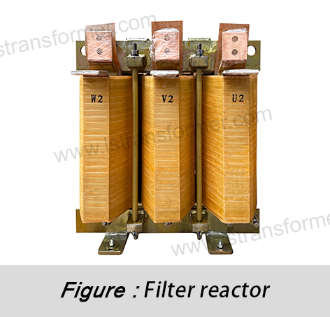
Pourquoi la distribution de l’augmentation de la température dans les réacteurs peut-elle être non uniforme ?
Pourquoi la distribution de l’augmentation de la température dans les réacteurs peut-elle être non uniforme ?
Dans les réseaux électriques, les réacteurs jouent un rôle indispensable dans la limitation du courant, le filtrage et la compensation de la puissance réactive. Cependant, les ingénieurs et le personnel de maintenance observent souvent des écarts de température importants à différents endroits d'un même réacteur. Cette augmentation non uniforme de la température affecte non seulement l'efficacité des équipements, mais menace également leur fiabilité et leur durée de vie à long terme. Alors, quelle est la cause exacte de cette répartition inégale de la température ? Cet article examine les mécanismes physiques sous-jacents, les principaux facteurs d'influence et les stratégies d'atténuation efficaces.
Menu
1. Densité de courant non uniforme : source des différences de production de chaleur
● Cause profonde :Selon la loi de Joule (Q = I² × R × t), la chaleur générée dans un conducteur est proportionnelle au carré du courant (I²). Lorsque le courant circule dans les enroulements d'un réacteur (en particulier dans les grands enroulements multicouches), sa distribution n'est pas parfaitement uniforme.
● Mécanismes détaillés :
(1)Effet sur la peau :Le courant alternatif a tendance à se concentrer près de la surface du conducteur, ce qui entraîne une densité de courant beaucoup plus élevée à la surface qu'au cœur. Les fréquences plus élevées accentuent cet effet, provoquant une production de chaleur significativement plus importante par unité de volume près de la couche externe du conducteur.
(2) Effet de proximité :Les conducteurs parallèles ou adjacents transportant un courant alternatif s'influencent mutuellement, ce qui entraîne une concentration du courant sur les côtés les plus proches des conducteurs voisins. Cela augmente encore la densité de courant et la production de chaleur dans certaines zones (notamment près des bords des conducteurs).
(3)Structure d'enroulement :Dans les enroulements multicouches, les différentes couches sont soumises à des environnements de champ magnétique variables. Les spires d'extrémité peuvent transmettre un flux de fuite plus important que les spires intermédiaires, ou de légères variations de longueur de spire (par exemple, aux extrémités de l'enroulement) peuvent entraîner de légères différences d'impédance et de densité de courant, affectant la production de chaleur.
● Résultat :Les zones à forte densité de courant (par exemple, les surfaces conductrices, les bords proches des conducteurs adjacents ou les positions de spires spécifiques) deviennent des « points chauds », générant beaucoup plus de chaleur par unité de volume et provoquant une surchauffe localisée.
2. Flux de fuite non uniforme : création de points chauds par pertes par courants de Foucault
● Cause profonde :En fonctionnement, les réacteurs produisent inévitablement un flux de fuite en plus du flux principal. La variation du flux de fuite (en particulier dans les réacteurs à courant alternatif) induit des courants de Foucault dans les composants métalliques (par exemple, noyaux, brides, cuves, blindages magnétiques), générant des pertes par courants de Foucault (P_eddy ∝ B² × f² × t²). La distribution du flux de fuite détermine directement l'ampleur de ces pertes.
● Mécanismes détaillés :
(1) Asymétrie structurelle :Les zones telles que les extrémités des enroulements, les sorties de fils, les joints de noyau ou les conduits de refroidissement proches présentent souvent des chemins magnétiques discontinus ou asymétriques, ce qui entraîne une densité de flux de fuite plus élevée (B).
(2)Concentration du flux :Le flux de fuite a tendance à se concentrer sur les bords du noyau, les coins des pinces ou les parois de la cuve, à proximité des enroulements. Des blindages magnétiques mal conçus peuvent également provoquer une densité de flux élevée localisée.
(3) Trajets des courants de Foucault :Dans les matériaux conducteurs (par exemple, l'acier au silicium et l'acier de construction), les variations de champ magnétique créent des courants de Foucault circulants. Les pertes par courants de Foucault sont proportionnelles au carré de la densité de flux locale ; les zones à fort flux de fuite subissent donc des pertes nettement plus élevées.
● Résultat :Les régions avec un flux de fuite concentré (par exemple, les extrémités d'enroulement, les bords du noyau ou les zones de réservoir localisées) deviennent des « points chauds de perte », générant une chaleur excessive et créant des températures élevées localisées importantes.
3. Variations des conditions de refroidissement : goulots d'étranglement dans la dissipation thermique
● Cause profonde :Selon la loi de Newton sur le refroidissement (Q = h × A × ΔT), la dissipation thermique dépend du coefficient de transfert thermique (h), de la surface (A) et de la différence de température (ΔT). Il existe des différences naturelles ou structurelles dans les conditions de refroidissement des réacteurs.
● Mécanismes détaillés :
(1) Différences d’emplacement interne :La chaleur provenant des spires internes des enroulements ou des tôles du noyau doit d'abord être transmise aux surfaces ou aux canaux de refroidissement avant d'être évacuée. Les zones internes profondes sont confrontées à de longs chemins de conduction et à une résistance thermique élevée, ce qui rend la dissipation thermique difficile. En revanche, les surfaces proches des canaux de refroidissement (par exemple, conduits d'huile, bouches d'aération, radiateurs) dissipent efficacement la chaleur.
(2) Débit de fluide de refroidissement non uniforme :
– Réacteurs immergés dans l’huile :L'écoulement de l'huile dans les conduits d'enroulement ou de noyau peut être irrégulier. Les zones étroites, courbées ou stagnantes (« zones à faible débit » ou « zones d'huile morte ») subissent un transfert de chaleur par convection réduit (h), ce qui entraîne une accumulation de chaleur. Les impuretés de l'huile peuvent également obstruer les voies d'écoulement.
– Réacteurs de type sec :La circulation d'air (naturelle ou forcée) peut être entravée par des structures sinueuses, la conception des conduits ou des obstacles à l'installation. Des zones comme les centres d'enroulement, les fonds ou les côtés sous le vent peuvent présenter une mauvaise circulation d'air ou des zones mortes, réduisant ainsi l'efficacité du refroidissement.
(3)Superficie limitée :Les composants structurels (par exemple, les pinces, les supports) ont souvent des formes complexes avec de petites zones de refroidissement efficaces et peuvent être situés dans des régions mal refroidies, ce qui entraîne des températures plus élevées que les enroulements ou les noyaux.
● Résultat :Les régions avec des chemins de chaleur obstrués ou un mauvais flux de fluide de refroidissement (par exemple, les enroulements internes, les profondeurs du noyau, les zones mortes huile/air ou les pièces structurelles) peuvent devenir des zones à haute température en raison de l'accumulation de chaleur, même si la production de chaleur n'est pas la plus élevée.
4. Propriétés des matériaux et résistance thermique de contact : obstacles à la conduction thermique
● Cause profonde :La conduction thermique suit la loi de Fourier (q = -λ × ∇T), où la conductivité thermique (λ) est critique. La résistance thermique aux interfaces des matériaux (résistance de contact) freine également le flux thermique.
● Mécanismes détaillés :
(1) Différences de conductivité des matériaux :Les réacteurs utilisent des matériaux divers :
-Conducteurs (Cu/Al) :Haute conductivité (λ ≈ 400/240 W/m·K).
-Isolation (papier, vernis, Nomex®, époxy) :Faible conductivité (λ ≈ 0.1–0.5 W/m·K).
-Laminations du noyau :Bonne conductivité dans le plan (λ ≈ 30–50 W/m·K), mauvaise conductivité dans le plan transversal.
-Acier de construction, huile, air :Faible conductivité (λ ≈ 40–50, 0.1–0.2, ~0.025 W/m·K).
(2) Résistance thermique de l'isolation :La chaleur des conducteurs doit traverser l'isolant, qui présente une résistance thermique élevée. Une isolation plus épaisse ou multicouche aggrave ce problème, emprisonnant la chaleur à l'intérieur des conducteurs.
(3) Résistance de contact :Un contact imparfait entre les tôles du noyau, les entretoises d'enroulement ou les interfaces d'assemblage (en raison de la rugosité, de l'oxydation, de la basse pression ou des revêtements) crée une résistance de contact élevée (R_contact), ce qui entrave gravement le transfert de chaleur.
● Résultat :Les matériaux faiblement conducteurs (en particulier l'isolation) et les interfaces à haute résistance de contact entravent le flux de chaleur des sources (conducteurs, noyaux) vers les surfaces ou supports de refroidissement, aggravant ainsi la surchauffe localisée.
5. Environnement externe et conditions de fonctionnement : amplificateurs de non-uniformité
● Cause profonde :L'environnement physique et l'état de fonctionnement du réacteur affectent directement le refroidissement global et la répartition des pertes internes.
● Mécanismes détaillés :
(1)Température ambiante :Les températures ambiantes élevées (Ta) réduisent le rapport de refroidissement du milieu au point chaud (ΔT), abaissant (Q) et aggravant les problèmes de point chaud.
(2) Lumière du soleil (installations extérieures) :La lumière directe du soleil chauffe les surfaces du réservoir ou de l’encapsulation, réduisant ainsi la capacité et aggravant indirectement le refroidissement interne.
(3) Mauvaise ventilation/contraintes d'espace :La circulation d'air restreinte autour des réacteurs de type sec ou des radiateurs entrave le refroidissement, augmentant les températures globales et les irrégularités.
(4)Courants harmoniques :Les charges non linéaires génèrent des harmoniques, augmentant les pertes parasites et par Foucault (P_loss ∝ I² × f). Ces pertes sont souvent inégalement réparties (par exemple, concentrées sur les surfaces), créant ou intensifiant des points chauds.
(5)Surcharge :Le fonctionnement en surintensité prolongé augmente toutes les pertes (I²R, courants de Foucault), augmentant les températures. Les goulots d'étranglement deviennent plus sensibles, aggravant la non-uniformité.
● Résultat :Les environnements difficiles (chaleur, soleil, mauvaise circulation d'air) et (harmoniques, surcharge) amplifient l'augmentation inhérente de la température, rendant les points chauds plus graves.
6. Stratégies clés pour atténuer l'augmentation non uniforme de la température
Comprendre ces causes permet un meilleur contrôle. La conception et la maintenance modernes des réacteurs s'appuient sur les stratégies suivantes :
● Conception électromagnétique optimisée :
(1)Utilisez des simulations avancées (par exemple, ANSYS Maxwell, JMAG) pour prédire et réduire les points chauds.
(2) Optimiser la transposition des enroulements, la conception du noyau et le blindage magnétique pour équilibrer les courants et contrôler le flux de fuite.
● Refroidissement amélioré :
(1)Immergé dans l'huile :Optimisez les conduits d’huile, utilisez une isolation à λ élevé, ajoutez des radiateurs ou un refroidissement forcé de l’huile.
(2)Type sec :Améliorez le flux d'air, utilisez une encapsulation à λ élevé et ajoutez un refroidissement localisé.
Appliquer des revêtements à haute émissivité pour booster
● Améliorations des matériaux et des processus :
(1) Utilisez une isolation à λ élevé, assurez une stratification serrée du noyau et remplissez les espaces avec des matériaux d'interface thermique.
● Surveillance intelligente :
(1)Installer des capteurs de température (fibre optique, Pt100) aux points chauds.
(2) Effectuer des inspections IR régulières et surveiller les harmoniques/charges.
L'augmentation non uniforme de la température des réacteurs est due à une densité de courant inégale, au flux de fuite, aux conditions de refroidissement, aux limitations des matériaux et à des facteurs externes. La prise en compte de ces facteurs grâce à une conception, un refroidissement, des matériaux et une surveillance avancés garantit un fonctionnement sûr, efficace et fiable dans le monde entier.
En ciblant l'augmentation de la température du réacteur, l'atténuation des points chauds et l'optimisation du refroidissement, cet article améliore la visibilité du référencement tout en fournissant des informations exploitables pour le public mondial.
Contactez-Nous
LuShan, HNE.1975, est un fabricant chinois spécialisé dans les transformateurs et réacteurs de puissance depuis plus de 50 ans. Ses principaux produits sont :Transformateur monophasé, transformateurs d'isolement triphasés, transformateur électrique, transformateur de distribution, transformateur abaisseur et élévateur, transformateur basse tension, transformateur haute tension, conTransformateur de commande, transformateur toroïdal, transformateur à noyau R; inductances CC, réacteurs CA, réacteur de filtrage, réacteur de ligne et de charge, selfs, réacteur de filtrage et produits intermédiaires à haute fréquence.
Nos transformateurs et réacteurs de puissance sont largement utilisés dans 10 domaines d'application : transport rapide, engins de chantier, énergie renouvelable, fabrication intelligente, équipement médical, prévention des explosions de mines de charbon, système d'excitation, frittage sous vide (four), climatisation centrale.
En savoir plus sur le transformateur de puissance et le réacteur :www.lstransformer.com.
Si vous souhaitez obtenir des solutions personnalisées pour les transformateurs ou les réacteurs, veuillez nous contacter.
WhatsApp:+86 17267488565
Courriel : marketing@hnlsdz.com

 EN
EN
 FR
FR DE
DE ES
ES


