 EN
EN
 FR
FR DE
DE ES
ES
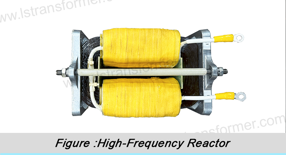
Exigences d'adaptabilité environnementale des réacteurs dans les systèmes de traction ferroviaire à grande vitesse
Pilier essentiel des transports modernes, le réseau ferroviaire à grande vitesse repose fortement sur la stabilité de son système de traction dans des conditions d'exploitation difficiles. Les réacteurs, composants critiques des convertisseurs de traction, influent directement sur la fiabilité et la sécurité des trains grâce à leur adaptabilité environnementale. Cet article propose une analyse approfondie des principales exigences d'adaptabilité environnementale des réacteurs dans les systèmes de traction des lignes ferroviaires à grande vitesse, ainsi que des principes techniques sous-jacents.
Contenu
1. Résistance aux vibrations et chocs mécaniques extrêmes
● Raison :
Les trains à grande vitesse circulent entre 250 et 350 km/h, où les irrégularités de la voie, les aiguillages et les perturbations aérodynamiques engendrent d'importantes vibrations et des chocs. Les données d'essais montrent que les composants embarqués critiques doivent résister à des vibrations aléatoires d'au moins 5 Grms (gamme de fréquences de 5 à 2 000 Hz) et à des chocs transitoires jusqu'à 50 g.
● Exigences clés :
-Fatigue-conception structurelle résistante :
Les châssis en alliage haute résistance, associés à des systèmes de suspension élastique multipoints, dispersent et absorbent efficacement l'énergie vibratoire. Les assemblages boulonnés critiques utilisent des rondelles anti-desserrage et un adhésif frein-filet pour éviter tout desserrage dû à l'usure par micromouvements.
-Renforcement par enroulement contre la déformation :
Les bobines sont imprégnées par imprégnation sous vide et pression (VPI) avec une résine époxy résistante et intercalées avec un matériau de renfort Nomex®. Ce procédé assure une pénétration profonde de la résine, formant après durcissement une structure monolithique en « fibre de verre » qui améliore considérablement la résistance mécanique et la fréquence naturelle, tout en évitant les fractures dues à la résonance.
-Noyau magnétique anti-Verrouillage du levier de vitesse :
Les tôles d'acier au silicium laminées sont assemblées par recouvrement étagé et comprimées sous une pression spécifique (par exemple, 15 à 20 MPa), complétée par un revêtement adhésif haute température. La force de serrage est calculée avec précision par analyse par éléments finis (AEF), garantissant ainsi le maintien d'entrefers uniformes dans l'âme sous l'effet des vibrations et évitant toute surchauffe locale due à la déformation du flux.
Article d'essai |
Degré de gravité |
Paramètre Description |
Objectif de vérification |
Vibration aléatoire (Long./Trans.) |
Classe 1 |
5–2000 Hz, 5 Grms (4 heures par axe) |
Intégrité structurelle, verrouillage par boulons |
Choc fonctionnel |
Classe 1 |
Onde demi-sinusoïdale, crête de 50 g, durée d'impulsion de 30 ms |
tolérance aux surcharges transitoires |
Vibrations opérationnelles à long terme |
- |
Spectre équivalent mesuré par raie, >10⁷ cycles |
résistance à la fatigue |
|
Tableau 1 : Exigences typiques en matière d'environnement mécanique pour les réacteurs ferroviaires à grande vitesse (selon la norme EN 61373)
2. Gestion thermique efficace sur une large plage de températures
● Raison :
Les pertes de puissance du réacteur (pertes par effet Joule I²R + pertes par effet Joule) se convertissent en chaleur, tandis que l'espace confiné et les conditions de refroidissement insuffisantes dans le compartiment de traction entraînent des températures ambiantes pouvant atteindre 70 °C en été. Parallèlement, l'élévation de température propre du réacteur (ΔT) doit être limitée à 80 K (selon la norme EN 61557), soit une température du point chaud ≤ 150 °C (limite d'isolation de classe H).
● Technologies de gestion thermique de base :
Application des matériaux à faibles pertes : On utilise des tôles d'acier au silicium à haute perméabilité et de faible épaisseur (0.23 mm), telles que celles de la série JNEH. Leurs pertes dans le noyau P <sub>1.7/50</sub> sont ≤ 0.98 W/kg. La formule des pertes par courants de Foucault

(K e : constante du matériau, t : épaisseur de la feuille) montre que la réduction de l'épaisseur t de 50 % diminue les pertes par courants de Foucault de 75 %.
Optimisation du système de refroidissement par air pulséUn conduit d'air composite axial-radial a été conçu, et des simulations de dynamique des fluides numérique (CFD) ont été utilisées pour déterminer l'angle optimal du déflecteur (par exemple, une inclinaison de 30°). Le système de refroidissement par air doit maintenir une vitesse de vent à la surface de l'enroulement ≥ 2 m/s et garantir un coefficient de transfert thermique par convection h > 50 W/(m²·K), même à une température d'air d'admission de 70 °C.
Conductivité thermique améliorée par imprégnation sous vide :Le procédé d'imprégnation sous vide (VPI) utilise une résine époxy à haute conductivité thermique (λ ≥ 0.8 W/m·K) pour remplir les interstices microscopiques des bobines. Conformément à la loi de Fourier

La résine durcie forme un chemin de conduction thermique continu, augmentant ainsi la conductivité thermique globale de l'enroulement.plusplus de 30 % par rapport aux procédés traditionnels.
3. Compatibilité électromagnétique (CEM) et performances anti-interférences élevées
● Raison :
Les convertisseurs de traction fonctionnent à des fréquences de commutation de l'ordre du kHz (par exemple, les IGBT à 2–5 kHz), avec un di/dt atteignant plusieurs milliers d'A/µs, générant ainsi de puissants champs électromagnétiques autour du réacteur. Les interférences électromagnétiques non supprimées peuvent perturber les systèmes de signalisation ferroviaire (par exemple, la communication sans fil 1750 MHz d'ATP).
● Points clés de conception CEM :
Structure à faible capacité parasite :
On adopte une conception d'enroulement segmentée (par exemple, un enroulement à 8 couches), avec un film de PTFE (εᵣ ≈ 2.1) inséré entre les couches. La formule de calcul de la capacité

indique que la réduction de la constante diélectrique εᵣ et de la surface A tout en augmentant la distance intercouche d peut réduire la capacité distribuée à 1/5 de celle des structures conventionnelles, supprimant ainsi les oscillations à haute fréquence.
Blindage électromagnétique multicouche :
Un blindage double couche est appliqué à l'extérieur du réacteur : la couche interne est constituée d'un blindage magnétique en cuivre de 1 mm d'épaisseur (absorbant les champs magnétiques basse fréquence), tandis que la couche externe est une coque de blindage électrique en aluminium avec un revêtement zinc-nickel (20 µm) (réfléchissant les champs électriques haute fréquence). Selon la formule de profondeur de pénétration

L'alliage nickel-zinc présente un δ ≈ 22 μm à 1 MHz, atténuant plus de 90 % du bruit rayonné.
Système de mise à la terre et de filtrage :
Toutes les couches de blindage sont connectées au bus de mise à la terre principal du convertisseur via des sangles de mise à la terre à faible impédance (< 2.5 mΩ), et un circuit d'amortissement RC (par exemple, 10 Ω + 100 nF) est installé à l'entrée de la bobine pour supprimer les pics de tension et les surtensions résonantes.
4. Tolérance à la haute altitude et aux environnements pollués
● Raison :
Les lignes ferroviaires à grande vitesse traversent souvent des régions situées à plus de 2 000 m d’altitude (par exemple, la ligne Qinghai-Tibet), où la densité de l’air n’est que de 75 % de celle au niveau de la mer, ce qui réduit la capacité de dissipation de chaleur d’environ 20 %. De plus, des contaminants comme la poussière et le brouillard salin peuvent provoquer des traces sur la surface d’isolation externe du réacteur.
● Solutions d’adaptation :
-Conception de réduction de puissance en altitude :
Selon la norme IEC 60664, la rigidité diélectrique diminue d'environ 10 % par tranche de 1 000 m d'altitude. Les conceptions intègrent une marge d'isolation de 20 % (par exemple, les produits de type plateau ont une tension de tenue à fréquence industrielle portée à 12 kV), et un film de polyimide résistant à l'effet corona (par exemple, Kapton® CR) est utilisé pour renforcer l'isolation intercouche.
-Anti-Procédé de revêtement par propagation éclair de la pollution :
Un caoutchouc silicone vulcanisable à température ambiante (RTV) est pulvérisé sur la surface d'isolation externe du réacteur, offrant un angle de contact hydrophobe supérieur à 105°. Lorsque des particules de brouillard salin adhèrent, le revêtement RTV forme un film hydrophobe par migration de chaîne moléculaire, brisant les films d'eau continus en gouttelettes isolées et bloquant les voies de fuite (les tests montrent que les valeurs CTI peuvent être augmentées jusqu'à 600 V).
-Anti-dispositif de chauffage par condensation :
Un élément chauffant PTC autorégulé (densité de puissance de 0.5 W/cm²) est intégré à la base du réacteur. S'activant automatiquement lorsque les capteurs d'humidité détectent une humidité relative supérieure à 85 %, il maintient la température de surface à au moins 5 °C au-dessus du point de rosée, empêchant ainsi les décharges superficielles dues à l'absorption d'humidité.
Menace environnementale |
Impact physique |
Mesures protectives |
Norme de vérification |
Basse pression atmosphérique (3000 m d'altitude) |
Résistance à l'isolation ↓20% |
Jeu extérieur ↑25%, tension de tenue ↑20% |
CEI 60076‑15 |
Corrosion par brouillard salin (côtière) |
Corrosion des métaux, conductivité de surface de l'isolant ↑ |
Protection du boîtier IP55, pièces en cuivre nickelé |
Test au brouillard salin ISO 9227 |
Accumulation de poussière (désert) |
Encrassement du dissipateur thermique, hausse de température ↑15 K |
Filtre à poussière + conception de soufflage périodique |
Test de poussière IEC 60529 |
Tableau 2 : Mesures de protection des réacteurs en milieu de haute altitude et pollué
5. Stabilité d'impédance sur une large gamme de fréquences
● Raison :
Les systèmes de traction modernes utilisent des topologies multiniveaux (par exemple, 3L-NPC) avec des spectres harmoniques de sortie complexes (incluant les bandes latérales ±1 et ±2 de la fréquence de commutation). Si l'impédance du réacteur fluctue de plus de ±15 % dans la bande 1–10 kHz, une défaillance du filtrage, voire une résonance, peut survenir.
● Principes techniques de stabilisation de fréquence :
-Noyau à entrefer réparti :
Des entretoises non magnétiques (par exemple, en céramique) sont insérées avec précision dans les tôles du noyau afin de répartir uniformément les entrefers. La réluctance magnétique totale montre que la répartition des entrefers réduit les effets de flux de bord aux extrémités de l'entrefer, garantissant ainsi la linéarité de l'inductance L sur toute la gamme de fréquences.
-Haute-Suppression des courants de Foucault par fréquence :
On utilise un fil de Litz composé de plusieurs brins (diamètre ≤ 0.3 mm) isolés individuellement. La formule des pertes par courants de Foucault indique qu'une réduction de 50 % du diamètre du fil (d) diminue les pertes à haute fréquence à un facteur 16, tout en conservant un facteur Q élevé (> 100) même à 10 kHz.
-Compensation de déformation thermique :
Un alliage à dilatation négative (par exemple, un alliage Invar, CTE ≈ 1.5 × 10⁻⁶/K) est intégré au support d'enroulement. Lorsque la température augmente de -40 °C à 125 °C, l'alliage se contracte pour compenser la dilatation de la résine époxy (CTE ≈ 50 × 10⁻⁶/K), maintenant ainsi l'écart d'inductance à ±5 %.
Conclusion
L'adaptabilité environnementale des réacteurs de traction des lignes ferroviaires à grande vitesse repose sur une intégration poussée des sciences des matériaux, de la mécanique des structures et de l'électromagnétisme. Des châssis en alliage conçus pour résister aux chocs aux revêtements nano-blindés optimisés pour la CEM, en passant par les systèmes de gestion thermique intelligents adaptables de -40 °C à 70 °C, chaque élément nécessite une conception précise grâce à une simulation collaborative multiphysique (par exemple, ANSYS Maxwell + Fluent).
Les normes internationales (par exemple, EN 50155 pour les équipements électroniques ferroviaires, IEC 60076 pour les transformateurs de puissance) constituent le cadre de référence pour l'adaptabilité environnementale des réacteurs. Les principaux fabricants améliorent constamment la durée de vie de leurs produits en conditions extrêmes (objectif : plus de 300 000 km sans maintenance) grâce à des matériaux innovants (dissipateurs thermiques composites SiC-Al), à une exploitation et une maintenance intelligentes (surveillance de la température et des vibrations par l'Internet des objets) et à la technologie du jumeau numérique.
Quels sont les défis environnementaux spécifiques auxquels votre projet de ligne ferroviaire à grande vitesse est confronté ? Contactez notre équipe d’ingénierie pour des solutions d’adaptation environnementale personnalisées des réacteurs et des rapports de conformité aux normes EN/IEC.
Contactez-Nous
LuShan, HNE.1975, est un fabricant professionnel chinois spécialisé dans les transformateurs de puissance et les réacteurs pour50 années. Les produits phares sont transformateur monophasé, triphasé seul transformateurs, transformateur électrique,transformateur de distribution, transformateur abaisseur et élévateur, transformateur basse tension, transformateur haute tension, transformateur de contrôle, transformateur toroïdal, transformateur à noyau R ;Inductances CC, réacteurs CA, réacteurs filtrants, réacteurs de ligne et de charge, selfs, réacteurs filtrants et produits intermédiaires à haute fréquence.
Notre pouvoir Les transformateurs et les réacteurs sont largement utilisés dans 10 domaines d'application : transport rapide, engins de chantier, énergie renouvelable, fabrication intelligente, équipement médical, prévention des explosions dans les mines de charbon, système d'excitation, frittage sous vide (four), climatisation centrale.
En savoir plus sur le transformateur de puissance et le réacteur :www.lstransformer.com.
Si vous souhaitez obtenir des solutions personnalisées pour les transformateurs ou les réacteurs, veuillez nous contacter.
WhatsApp:+86 13787095096
Courriel : [email protected]