Comment détecter à l'avance les points chauds des enroulements de transformateurs grâce à l'imagerie thermique infrarouge ? — Principaux enseignements technologiques d'experts mondiaux du secteur de l'énergie
How to Detect Transformer Winding Hotspots in Advance Using Infrared Thermal Imaging?
—Key Technology Insights from Global Power Experts
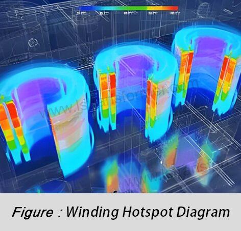
In transformer lifecycle management, excessive winding hotspot temperatures are a primary cause of accelerated insulation degradation and eventual failure. Global power grid statistics reveal that over 35% of unplanned transformer outages are directly linked to winding overheating. Infrared thermal imaging technology, with its non-contact, visual, and high-sensitivity advantages, has become a core method for international power equipment condition monitoring (IEC 60478, IEEE C57.127). This article provides an in-depth analysis of how to systematically apply this technology for early hotspot detection.
1. The Science Behind Winding Hotspot Formation and Infrared Monitoring
Root Causes: Winding hotspots are essentially areas of localized increased resistive losses (Joule heating) or impaired heat dissipation. Key contributing factors include:
(1)Abnormal Contact Resistance Increase: Poor solder joints, loose bolt connections, or worn/oxidized tap changer contacts lead to higher contact resistance, generating excessive heat (P = I²R).
(2)Conductor Defects:Broken wires or damaged insulation distort current distribution, causing localized high current density.
(3)Magnetic Circuit Loss Concentration:Core multi-point grounding, laminated core short circuits, or stray flux inducing eddy currents in structural components (clamps, tanks).
(4)Pannes du système de refroidissement : Blocked oil channels, mistakenly closed radiator valves, failed cooling fans/oil pumps, or degraded oil thermal conductivity.
Infrared Thermal Imaging Principle:All objects above absolute zero emit infrared radiation energy correlated with their temperature and surface properties. Infrared cameras use precision detectors to capture surface infrared radiation flux density and convert it into temperature distribution images based on the Stefan-Boltzmann law:
E = ε × σ × T⁴
(1)E: Surface radiant flux density (W/m²)
(2) :Material emissivity (0 ≤ ε ≤ 1; typically 0.85–0.95 for transformer oil or oxidized metal surfaces)
(3) : Stefan-Boltzmann constant (5.67 × 10⁻⁸ W/(m²·K⁴))
(4)T:Absolute temperature of the object (K)
Composant |
Typical Surface Condition |
Recommended Emissivity (ε) |
Remarques |
Corps de réservoir |
Aged outdoor coating |
0.90 – 0.95 |
Refer to new paint values |
Traversée haute tension |
Ceramic/composite material |
0.85 – 0.93 |
Highly affected by contamination |
Radiator Fins |
Métal peint |
0.85 – 0.90 |
|
Oil Pump/Fan Housing |
Métal peint |
0.85 – 0.90 |
|
Bare Copper Conductor |
Oxidized surface |
0.60 – 0.80 |
Nécessite une configuration minutieuse |
Laminated Core Surface |
Insulated coating |
0.75 – 0.85 |
Usually not visible |
Table 1: Reference Emissivity Values for Common Transformer Components (Based on IEEE Std C57.127)
2. Best Practices for Infrared Thermal Imaging Detection of Winding Hotspots (Compliant with IEC 62446)
● Equipment Selection and Environmental Preparation
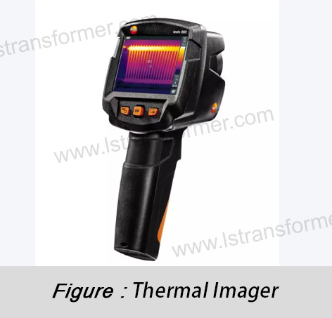
(1)Thermal Camera Requirements: Use mid-to-long-wave (3–5 μm or 8–14 μm) models with thermal sensitivity (NETD) ≤ 0.05°C and spatial resolution (IFOV) ≤ 1.5 mRad. Ensure lens coverage of target areas.
(2)Optimisation environnementale :
- Load Conditions: Ideal detection load ≥ 40% of rated capacity (per IEC 62446) to ensure measurable thermal effects. Record real-time load current and oil temperature.
- Interference Avoidance: Avoid strong sunlight, rain/snow/fog, or high winds (> Level 6). Nighttime scans yield optimal results.
- Distance and Angle: Maintain a distance of 3–5 times the equipment height (e.g., 15 meters). Keep the lens axis ≤ 30° from the surface normal (or apply emissivity correction).
● Comprehensive Scanning and Key Area Focus
(1)Scan complet:Systematically scan the transformer exterior to generate a panoramic thermal map. Focus on:
- High/low-voltage bushing roots and current-carrying connections.
- Cooler inlet/outlet pipes and valve areas.
- Tank walls near winding locations (requires structural knowledge).
- On-load tap changer (OLTC) tanks and drive mechanisms.
(2)Identification des points d'accès :Flag areas with temperatures significantly higher (> 5°C) than surrounding regions.
● Precise Temperature Measurement and Interference Mitigation
(1)Emissivity Correction: Set accurate ε values per Table 1. For new/refurbished equipment, obtain manufacturer coating data.
(2)Reflection Artifact Removal: Identify and eliminate reflections from ambient heat sources (e.g., sunlight, HVAC). Temporarily block suspected sources for verification.
(3)Oil Film Compensation: Account for surface temperature drops (typically 1–3°C) due to oil films on bushings.
● Temperature Differential Analysis and Hotspot Evaluation
(1)Relative Temperature Differential (ΔT_rel): The core diagnostic metric:
ΔT_rel = (T_hotspot - T_reference) / (T_reference - T_ambient) × 100%
T_hotspot:Hotspot peak temperature (°C)
T_référence: Normal temperature of a comparable component under the same conditions (e.g., symmetrical bushing).
T_ambiant : Température ambiante (° C)
(2)Absolute Temperature Assessment:Refer to insulation thermal class (e.g., Class A: 105°C, Class B: 130°C).
ΔT_rel |
T_hotspot |
Niveau de risque |
Action d'entretien |
<% 20 |
< 90°C (Oil-immersed) |
Faible risque |
Document; monitor in next inspection |
20-50% |
90-110 ° C |
Risque moyen |
Increase inspection frequency (1–3 months) |
> 50% |
> 110 ° C |
Risque élevé |
Schedule immediate outage for diagnostics |
N/D |
> 140 ° C |
Critical |
Emergency shutdown! Risk of rapid insulation carbonization |
Table 2: Hotspot Risk Assessment Matrix (Based on IEEE C57.91 & IEC 60599)
3. Beyond Basics: Advanced Diagnostics and Predictive Maintenance Strategies
● Hotspot Root Cause and Fault Mode Identification
(1)Surchauffe interne : Localized high-temperature zones on the tank wall (aligned with internal windings), with temperature rise rates strongly correlated to load current. Accompanied by abnormal top-oil temperature.
(2)External Connection Faults: Point/small-area hotspots at bushing terminals, cable ends, or busbar joints; ΔT_rel is typically high (> 50%).
(3)Pannes de refroidissement : Abnormal radiator temperature distribution (e.g., reduced inlet/outlet differential, cold tubes).
● Trend Analysis and Lifespan Assessment
(1)Établissement de la base de référence :Create reference temperature distribution maps at typical loads after commissioning/overhaul.
(2)Quantify Trends: Log key point temperatures and ΔT_rel over time. Temperature rise rate (°C/month) is critical for fault prediction.
(3)Insulation Lifespan Loss: Per Arrhenius model, every 6°C rise (oil-immersed) halves insulation paper life (IEEE C57.91).
● Closed-Loop Maintenance Decision Support
(1)Low/Medium Risk: Combine with dissolved gas analysis (DGA) to check for overheating gases (H₂, CH₄, C₂H₄, CO, CO₂).
(2)Risque élevé: Reduce load and plan outage. Prioritize high-frequency partial discharge tests or frequency response analysis (FRA) to assess internal damage.
(3)External Faults: Live-line repairs (e.g., bolt tightening guided by IR) or short outages for contact refurbishment.
4. Global Perspectives: Cutting-Edge Technology Integration and Standards Evolution
Leading utilities (e.g., BP, National Grid) combine infrared imaging with distributed temperature sensing (DTS):
(1)IR:Rapid global scanning for anomaly detection.
(2)La fibre optique: Embedded sensors in critical windings provide real-time absolute temperatures (±0.5°C accuracy).
(3)Diagnostic IA :Machine learning analyzes historical thermal images for automated anomaly detection (e.g., Google DeepMind’s substation monitoring).
●Evolving Standards:
(1)IEC 62446-3 (2023 Draft): New guidelines for IR in solar/storage plants, including transformer inspections.
(2)ISO 18436-7 :Stricter certification requirements for thermal imaging operators.
(3)Avis d’expert du secteur :
“Infrared thermal imaging is the cornerstone of transformer predictive maintenance. Substations adhering to IR protocols see up to 70% fewer unexpected failures. Success hinges on baseline tracking, precise emissivity settings, and ΔT_rel-based risk quantification.”
En résumé
Infrared thermal imaging transforms elusive electrical faults into precise, visual temperature maps. By applying scientific emissivity settings, complying with IEC/IEEE standards, and tracking ΔT_rel trends, operators gain extended warning windows for winding hotspots.
As global energy infrastructure demands grow, integrating IR into predictive maintenance (PdM) programs is now a best practice for avoiding outages, optimizing costs, and ensuring grid stability. Adopt this technology to proactively safeguard critical assets, extend service life, and maximize ROI. Act now—make infrared thermal imaging your operational “eagle eye.”
Contactez-Nous
LuShan, HNE.1975, est un fabricant professionnel chinois spécialisé dans les transformateurs de puissance et les réacteurs pour50+ années. Les produits phares sont transformateur monophasé, triphasé seul transformateurs, transformateur électrique,transformateur de distribution, transformateur abaisseur et élévateur, transformateur basse tension, transformateur haute tension, transformateur de contrôle, transformateur toroïdal, transformateur à noyau R ;Inductances CC, réacteurs CA, réacteurs filtrants, réacteurs de ligne et de charge, selfs, réacteurs filtrants et produits intermédiaires à haute fréquence.
Notre pouvoir Les transformateurs et les réacteurs sont largement utilisés dans 10 domaines d'application : transport rapide, engins de chantier, énergie renouvelable, fabrication intelligente, équipement médical, prévention des explosions dans les mines de charbon, système d'excitation, frittage sous vide (four), climatisation centrale.
En savoir plus sur le transformateur de puissance et le réacteur :www.lstransformer.com.
Si vous souhaitez obtenir des solutions personnalisées pour les transformateurs ou les réacteurs, veuillez nous contacter.
WhatsApp:+86 17267488565
Courriel : marketing@hnlsdz.com

 EN
EN
 FR
FR DE
DE ES
ES


