






What Are the Requirements for Parallel Operation of Transformers?
What Are the Requirements for Parallel Operation of Transformers?
In critical applications such as power systems, industrial facilities, and data centers, ensuring continuous and reliable power supply is paramount. Transformers, being the core equipment for electrical energy transmission and distribution, can be operated in parallel to enhance system capacity, redundancy, and flexibility. In simple terms, parallel operation of transformers involves connecting the primary (high-voltage) sides and secondary (low-voltage) sides of two or more transformers to common busbars, allowing them to supply power to the load cooperatively.
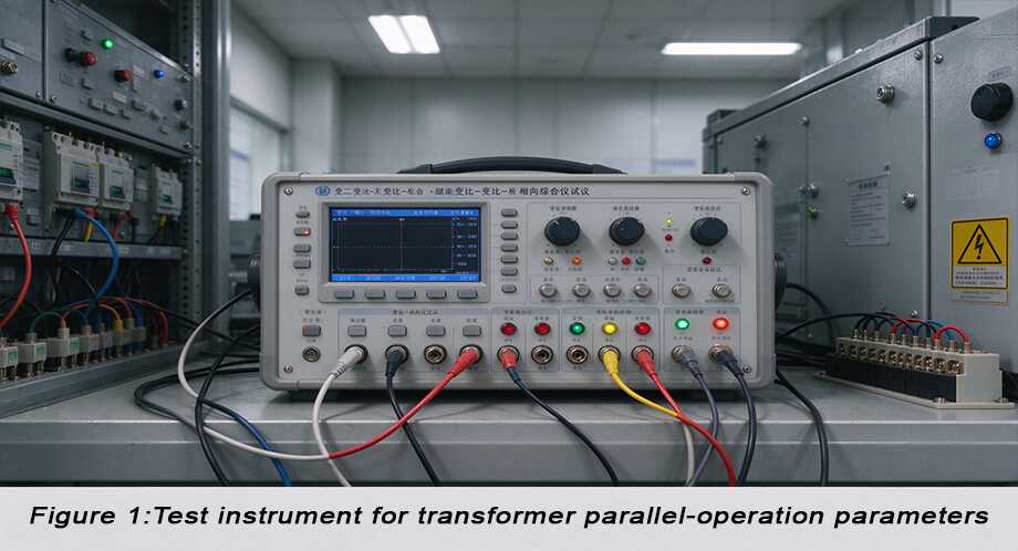
1. In-Depth Analysis of Core Conditions and Principles for Parallel Transformer Operation
To achieve safe, efficient, and economical parallel operation, the following four fundamental conditions must be met. These conditions are interrelated and collectively ensure the transformers “coexist harmoniously” rather than “compete with each other.”
1.1. Equal Voltage Ratio
1.1.1. Condition
The rated voltage ratio (the ratio of primary voltage to secondary voltage) of all transformers participating in parallel operation must be strictly identical. This is the most basic prerequisite.
1.1.2. Cause and Effect Logic
(1) Cause (Unequal Voltage Ratio):
Assume two transformers, Tr1 and Tr2, have slightly different voltage ratios, i.e., k1 = U1n/U2n1 ≠ k2 = U1n/U2n2. Even if their primary sides are connected to the same busbar and experience the same voltage U1, their secondary-side no-load voltages will differ: U201 = U1/k1, U202 = U1/k2.
(2) Effect (Circulating Current Generation):
When these two secondary sides with different voltages are connected to the common busbar, a voltage difference ΔU = U201 – U202 will exist in the closed secondary circuit. This voltage difference drives a current to circulate between the secondary windings of the transformers, even when the external load is zero. This current is called circulating current.
(3) Measures and Outcome:
Ensuring identical voltage ratios makes the secondary no-load voltages equal, fundamentally eliminating the voltage source that creates circulating currents. In practice, the deviation in voltage ratio is typically required to be within ±0.5%. This is guaranteed through strict manufacturing and factory testing (e.g., turns ratio test). Modern digital substations can monitor voltage ratio changes in real-time via online monitoring systems.
1.2. Same Vector Group
1.2.1. Condition
The winding connection method and the resulting phase relationship of the secondary voltages must be exactly the same for all transformers operating in parallel. This is typically indicated by the vector group symbol, such as Dyn11, YNd11, Yyn0, etc.
1.2.2. Cause and Effect Logic & Detailed Explanation
(1) Cause (Different Vector Groups):
Transformer windings can be connected in star (Y) or delta (D), resulting in a specific phase shift (usually a multiple of 30 degrees) between the primary and secondary voltages. For example, if a Dyn11 transformer is paralleled with a Yyn0 transformer, even if their voltage magnitudes are the same, their secondary voltages will have a 30-degree phase difference.
(2) Effect (High Circulating Currents & Short-Circuit Effect):
This phase difference creates a significant voltage difference at the paralleling point. This voltage difference is much larger than that caused by a minor discrepancy in voltage ratio. It will generate very high circulating currents in the windings, potentially reaching several times the rated current. This is equivalent to an internal short-circuit, rapidly leading to winding overheating, insulation damage, or even transformer burnout.
(3) Measures and Outcome:
The vector group must be explicitly specified and unified for all paralleled transformers during the design and selection phase. This is a non-negotiable “hard requirement.” Most global distribution systems prefer the Dyn11 vector group due to its benefits in suppressing third harmonics and providing a neutral point.
1.3. Equal Short-Circuit Impedance (Per-Unit Value)
1.3.1. Condition
The per-unit (percentage) values of the short-circuit impedance or impedance voltage for paralleled transformers should be as equal as possible. This is key to achieving proper load sharing.
1.3.2. Cause and Effect Logic & Detailed Explanation
(1) Cause (Unequal Short-Circuit Impedance):
A transformer’s short-circuit impedance (Zk%) represents the combined effect of its internal winding resistance and leakage reactance. It determines the internal voltage drop under load and the ability to withstand short-circuit currents. When two transformers with different Zk1% and Zk2% are paralleled, they present a parallel impedance circuit to the external load.
(2) Effect (Uneven Load Distribution):
According to the current division principle in parallel circuits, the current flowing through each transformer is inversely proportional to its impedance. Since the system voltage is the same, the load current distribution is effectively inversely proportional to the per-unit short-circuit impedance. This can be approximated by the formula: S1/S1N : S2/S2N ≈ Zk2% / Zk1%, where S1, S2 are the actual loads and S1N, S2N are the rated capacities. Thus, the transformer with the lower short-circuit impedance will carry a larger share of the load.
(3) Measures and Outcome:
Selecting transformers with identical per-unit short-circuit impedance for parallel operation allows each to share the total load in proportion to its rated capacity, maximizing utilization and preventing premature overloading of one unit. IEC standards recommend that the deviation in short-circuit impedance between paralleled transformers should not exceed ±10% of the average value. For scenarios where deviations exist, load sharing can be assessed using capacity-weighted calculations.
2. Essential Checks and Operational Procedures Before Parallel Operation
After confirming the four basic conditions above, the following steps must be executed in practice:
(1) Phase Verification:
Before initial paralleling or after maintenance, verify that the phase angle of the secondary voltage of the transformer to be connected matches exactly (is “in sync”) with the phase angle of the voltage on the live busbar. This must be done under no-load conditions using a phase meter or synchronism-check device.
(2) Voltage Difference Adjustment:
Even with identical voltage ratios, no-load voltages might still have minor differences due to tap changer positions or system voltage fluctuations. Operate the tap changer so that the secondary voltage of the transformer to be connected is slightly higher (by about 0.5-1%) than the busbar voltage. This allows it to pick up a small load smoothly after closing the circuit breaker.
(3) Impedance Matching Calculation:
Perform detailed calculations on the short-circuit impedance, as indicated in the principles, to predict load distribution and use this as a benchmark for operational monitoring.
(4) Protection Coordination:
Ensure the relay protection settings (e.g., overcurrent protection, differential protection) for each transformer are coordinated according to the parallel operation scenario. This prevents nuisance tripping while ensuring selective fault clearance.
| Check Item | Target/Requirement | Tools/Methods | International Standard Reference |
| Voltage Ratio | Deviation < ±0.5% | Turns Ratio Tester | IEC 60076-1 |
| Vector Group | Exactly the same | Nameplate verification, Phase Test Meter | IEC 60076-1 |
| Short-Circuit Impedance | Deviation < ±10% (based on capacity-weighted average) | Short-Circuit Impedance Tester | IEC 60076-5 |
| Capacity Ratio | Recommended ≤ 3:1 | System Design Review | IEEE C57.12.00 |
| Phase Sequence & Angle | Perfect match | Phase Meter / Synchronism-Check Device | IEEE C57.12.10 |
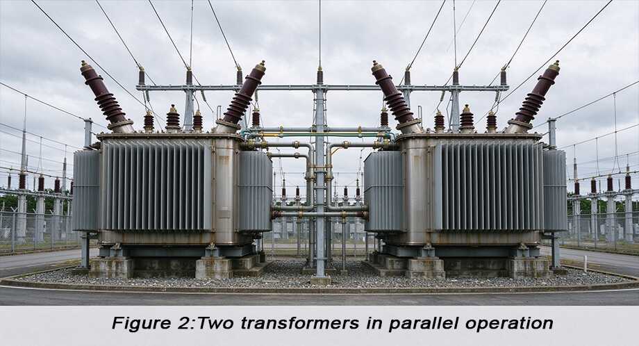
Conclusion and Global Best Practices
In summary, successful parallel operation of transformers is a highly technical systems engineering task. It involves more than just simple electrical connection; it is a comprehensive test of equipment parameter matching, system design, and operational procedures. The core conditions—equal voltage ratio, identical vector group, similar short-circuit impedance, and a reasonable capacity ratio—together form the cornerstone of reliable parallel operation.
Contact
LuShan, est. 1975, is a Chinese professional manufacturer specializing in power transformers and reactors for 50+ years. Leading products are single-phase transformer, three-phase isolation transformers, electrical transformer, distribution transformer, step down and step up transformer, low voltage transformer, high voltage transformer, control transformer, toroidal transformer, R-core transformer; DC inductors, AC reactors, filtering reactor, line and load reactor, chokes, filtering reactor, and intermediate, high-frequency products.
Our power transformers and reactors are widely used in 10 application areas: rapid transit, construction machinery, renewable energy, intelligent manufacturing, medical equipment, coal mine explosion prevention, excitation system, vacuum sintering(furnace), central air conditioning.
Know more about power transformer and reactor: www.lstransformer.com.
If you would like to obtain customized solutions for transformers or reactors, please contact us.
WhatsApp:+86 13787095096
Email: marketing@hnlsdz.com