 EN
EN
 FR
FR DE
DE ES
ES
How to Determine Transformer Insulation Performance Through Temperature Rise Test? – Key Guidelines Explained
In global power grid infrastructure, the stable operation of transformers is fundamental to electrical safety. The Temperature Rise Test serves as a core evaluation method directly impacting transformer insulation system reliability and service life. This article details the principles of the test, key execution points, and how it reveals insights into insulation performance.
Content
1. Core Principles and Purpose of the Temperature Rise Test
Thermal Degradation of Insulation Materials is one of the primary causes of transformer failure. High temperatures accelerate the chemical decomposition process of insulating materials (such as insulating oil and cellulose solid insulation in oil-paper composite systems), leading to a sharp decline in their electrical and mechanical strength, ultimately causing insulation failure or even catastrophic faults.
The Temperature Rise Test simulates transformer operation under rated load or specified overload conditions, measuring the temperature increase (temperature rise) at critical points when they reach a stable thermal state. Its main objectives are to verify:
● Whether measured temperature rises meet design expectations and international standard limits:
Ensuring that during long-term rated operation, the internal hottest-spot temperature does not exceed the withstand limit of the used insulation material class.
● The effectiveness of the cooling system:
Verifying if the design and performance of cooling devices (like radiators, fans, oil pumps) meet heat dissipation requirements.
● Detection of structural defects:
Revealing abnormal local hot spots, which often signal potential insulation threats such as winding deformation, poor contacts, excessive stray losses, or blocked cooling ducts.
2. Key Steps and Measurement Methods for the Temperature Rise Test
Tests are typically conducted in manufacturing plants or independent laboratories, strictly following procedures and environmental conditions (e.g., ambient temperature stability) stipulated by international standards like IEC 60076-2 / IEEE C57.12.90 / ANSI C57.12.90.
● Initial State Recording:
Measure and record the temperatures of all test points(windings, top oil, bottom oil, core, structural parts, etc.) and the ambient temperature before starting the test.
● Load Application & Temperature Monitoring:
Apply power loss equivalent to the rated current or specified load (primarily winding I²R copper loss and core loss) using the short-circuit method (more common) or load method (directmethod).
● Continuously monitor and record temperature changes at all key points. Measurement methods are crucial:
—Winding Resistance Method (Most Accurate):
Calculate average temperature rise by measuring DC resistance of windings in cold (pre-test) and hot states (immediately after de-energization), utilizing the linear relationship between resistance and temperature. Formula:
∆θ_w = (R_h - R_c) / R_c * (T + k)
Where:
∆θ_w = Winding temperature rise (°C or °F)
R_h = Hot-state winding resistance measured immediately after de-energization (Ω)
R_c = Cold-state winding resistance at test start (Ω)
T = Constant (234.5 for copper, 225 for aluminum, unit °C; adjust accordingly for °F)
k = Cooling medium temperature at test end (°C or °F)
—Top-Oil Temperature Measurement:
Use sensors immersed in the top oil (e.g., Pt100 platinum resistors).
—Hot-Spot Temperature Estimation Temperature Estimation:
Direct measurement is extremely difficult; standards (e.g., IEC 60076-7) estimate it by adding a calculated "hot-spot-to-top-oil gradient" based on load current and design parameters to the top-oil temperature.
—Infrared Thermography (Auxiliary):
Used to scan external components like tanks, radiators, bushings to help identify local overheating anomalies.
● Achieving Thermal Stability:
Maintain applied load until temperature changes at all measured points do not exceed a specified value (e.g., 1-2°C/hour) over consecutive hours (typically 3-4 hours).
● Final Measurements & Calculations:
— Record final stabilized temperatures at measurement points and final ambient temperature.
— Calculate Temperature Rise:
∆θ=θ_final -θ_ambient_final
Where:
•∆θ = Measured point temperature rise (°C or °F)
•θ_final = Final stabilized temperature of the measured point (°C or °F)
•θ_ambient_final = Final ambient temperature (°C or °F)
•For windings, average temperature rise is usually calculated via the resistance method.
3. Data Analysis and Insulation Performance Qualification Judgment
The core criterion for judging insulation performance qualification is whether the measured temperature rises (especially average winding rise and estimated hot-spot rise) are below the maximum allowable limits specified for the insulation material's thermal class. Standards likeIEC 60076-2 provide clear regulations.
Insulation System Thermal Class | Max Allowable Hot-Spot Temp (°C) | Typical Avg Winding Rise Limit (Resistance Method, °C) | Top-Oil Temp Rise Limit (°C) | Example Materials |
A (105) | 105 (120 Short-time) | 60 (ONAN) / 65 (OFAF) | 55 (ONAN) / 60 (OFAF) | Impregnated paper, cotton yarn |
E (120) | 120 | 75 | 65 | Synthetic resin impregnated materials |
B (130) | 130 (140 Short-time) | 80 (ONAN) / 85 (OFAF) | 65 (ONAN) / 70 (OFAF) | Mica, glass fiber, resin |
F (155) | 155 (175 Short-time) | 100 (ONAN) / 115 (OFAF) | 70 (ONAN) / 80 (OFAF) | High-performance resins, mica, glass fiber |
H (180) | 180 (220 Short-time) | 125 (ONAN) / 140 (OFAF) | Not specified | Silicone organic materials, mica |
Table 1: Common Insulation System Thermal Classes & Their Temperature Limits(Based on IEC 60076-2/IEEE C57.12.00 Summary)
Qualification Logic:
● Insulation Class Compatibility:
Measured temperature rise must be lower than the limit corresponding to the declared insulation thermal class of the transformer. For example, an 'F' class transformer should not exceed 100°C average winding rise (resistance method, ONAN cooling), with estimated hot-spot temperature not exceeding 155°C.
● No Local Overheating:
All component (core, structural parts, tank surface) temperature rises should be within reasonable ranges without significant localized hot spots markedly higher than similar parts. Abnormal local heating often signals early warnings of impending insulation failure, causing accelerated local thermal degradation.
● Compliance with Specific Standards:
Results must holistically satisfy all relevant temperature rise clauses in the contractually agreed International/National Standards (IEC, IEEE, ANSI, etc.).
Why Do Temperature Rise Limits Judge Insulation Performance?
•Material Life Model (Arrhenius Equation):
Insulation material aging rate approximately follows the Arrhenius law – roughly doubling for every 6-10°C increase (depending on material), halving its lifespan accordingly. The test verifies if the internal hottest-spot temperature remains within the safe range for long-term operation under continuous full load, preventing premature failure due to accelerated aging from thermal stress.
•Insulating Oil Deterioration:
Excessive oil temperature accelerates oxidation, producing acids and sludge. Acids corrode solid insulation and metals, reducing performance; sludge blocks cooling ducts, worsens temperature rise, lowers breakdown voltage.
4. Potential Insulation Issues Indicated by Abnormal Temperature Rise
Non-compliant or abnormal results strongly indicate underlying insulation issues:
Abnormal Phenomenon | Possible Causes | Impact on Insulation Performance |
Overall Temperature Rise Exceeds Limit | Design flaws (excessive losses, insufficient cooling surface); Cooling system failure (fan/pump stoppage, blockage); Overload | Accelerates overall thermal aging, shortening lifespan, increasing risk of sudden breakdown |
High/Localized Winding Temp Rise | Winding turn-to-turn shorts; Poor conductor contact; Excessive eddy currents from stray flux; Blocked cooling ducts | Local overheating carbonizes paper insulation, cracks oil, drastically reduces dielectric strength, prone to short circuits |
High Top-Oil Temperature Rise | Restricted oil flow (pump fault, pipe blockage); Low radiator efficiency (dirt, fan fault); Low oil level | Accelerates oil oxidation, increases acidity, degrades oil insulation properties and cooling ability, corrodes solid insulation |
High/Localized Core/Structural Part Temp Rise | Core ground faults; Excessive eddy currents in clamps/bolts; Severe stray flux | Risk of igniting insulation/oil; Gases from overheating may affect DGA analysis interpretation |
Localized Tank Surface Overheat | Internal areas of high eddy current loss; External magnetic shielding issues | May reflect internal insulation design/manufacturing defects, posing significant long-term risks |
Table 2: Abnormal Temperature Rise Phenomena vs. Potential Insulation Defects
Conclusion
Far more than just a routine check, the Temperature Rise Test acts as a crucial "thermometer" diagnosing the long-term operational reliability of a transformer's insulation system. By precisely measuring and scientifically analyzing if temperature distributions and rises comply with international standards and design insulation classes under simulated full-load conditions, we can effectively predict its insulation health status.
A successful test signifies that even under demanding continuous loads, the transformer's "heart" (insulation system) operates within safe temperature bounds, avoiding damage from thermal degradation. This ensures decades of reliable service, forming a robust foundation for grid stability, reduced outages, and lower maintenance costs.
For power users, grid operators, and manufacturers alike, rigorously conducting standardized Temperature Rise Tests is indispensable for selecting, accepting, and ensuring high-quality transformer insulation performance – a globally recognized best practice.
Contact Us
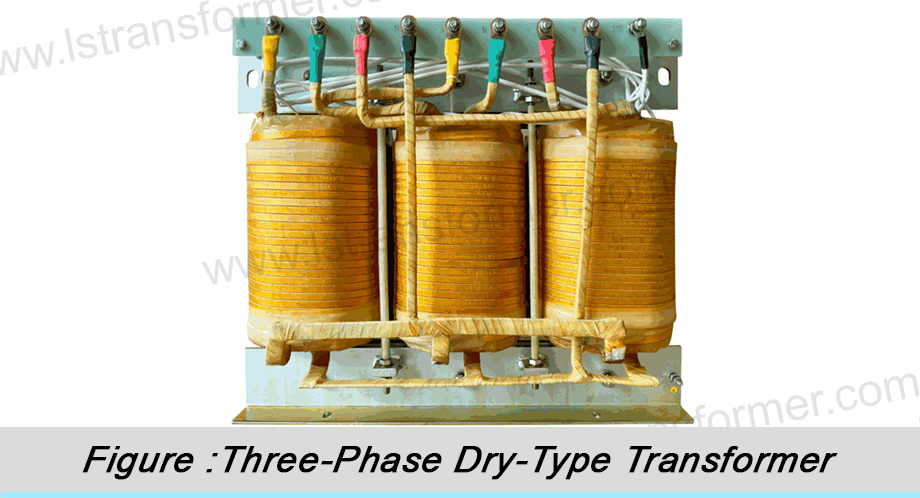
LuShan, est.1975, is a Chinese professional manufacturer specializing in power transformers and reactors for50+ years. Leading products are single-phase transformer, three-phase isolation transformers,electrical transformer,distribution transformer, step down and step up transformer, low voltage transformer, high voltage transformer, control transformer, toroidal transformer, R-core transformer;DC inductors, AC reactors, filtering reactor, line and load reactor, chokes, filtering reactor, and intermediate,high-frequency products.
Our power transformers and reactors are widely used in 10 application areas: rapid transit, construction machinery, renewable energy, intelligent manufacturing, medical equipment, coal mine explosion prevention , excitation system, vacuum sintering(furnace), central air conditioning.
Know more about power transformer and reactor :www.lstransformer.com.
If you would like to obtain customized solutions for transformers or reactors, please contact us.
WhatsApp:+86 13787095096
Email:[email protected]