






How to prevent Transformer Sudden Short-Circuit Failure? —Analyzing Short-Circuit Resistance Verification and Structural Reinforcement Solutions
How to prevent Transformer Sudden Short-Circuit Failure?
—Analyzing Short-Circuit Resistance Verification and Structural Reinforcement Solutions
In power grid systems and industrial distribution, “transformer sudden short-circuit leading to winding deformation and insulation breakdown” has become a global challenge for electrical equipment reliability. According toIEEE C57.12.00 statistics, short-circuit current impacts can subject windings to electromagnetic forces exceeding 100 kN, causing 40% of transformers to fail after their first short-circuit event. This article systematically explains short-circuit resistance verification processes and structural reinforcement technologies based on international standards likeIEC 60076-5 and IEEE C57.12.90, supported by cross-regional engineering validation data.
Content
1. Destruction Mechanism and Risk Quantification of Short-Circuit Current
1.1 Electromagnetic Force Impact of Short-Circuit Current
1.1.1 Short-Circuit Current Calculation and Electromagnetic
Force Generation When a short-circuit occurs on the transformer’s secondary side, the primary current surges to 10–25 times its rated value, determined by the transformer’s impedance voltage percentage (%).
(1) Formula:

(2) Variable Definitions:
 : System rated voltage
 : Impedance voltage percentage (typical range: 4%–12%)
 : Transformer rated current
(3) Example: A 1000 kVA transformer with Z%=6% and Irated = 1443A has a short-circuit current of:


1.1.2 Direct Mechanical Damage from Electromagnetic
Forces Per the Lorentz force formula, electromagnetic forces between adjacent winding conductors are:

(1) Variable Definitions:
 : Leakage flux density (0.5–1.2 T, determined by winding spacing and current)
 :Short-circuit current
 : Conductor effective length
(2) Example:If B=0.8T and L=2m, the force is: F=0.8×24,050×2=38,480N(≈38.5kN)
(3) Failure Modes:
Axial Compression: High-voltage windings experience inward pressure, leading to inter-turn insulation crushing.
Radial Expansion: Low-voltage windings expand outward, causing support strut fractures and eventual collapse.
1.2 Thermal Effects and Insulation Degradation
1.2.1 Joule Heating Mechanism:
Short-circuit current generates heat via winding resistance:

(1) Variable Definitions:
R: Winding resistance (Ω)
t: Short-circuit duration (typically ≤2 seconds)
c: Specific heat capacity (copper: 385 J/kg·K)
m: Conductor mass
(2) Example: For a 50 kg copper conductor with AIsc =24kA and t=1s:

1.2.2 Insulation Failure Process:
(1) Thermal Decomposition: Epoxy resin carbonizes when temperatures exceed 105°C (Class A insulation limit).
(2) Dielectric Strength Reduction: Insulation paper breakdown voltage drops 5%–8% per 10°C rise (IEC 60076-5).
(3) Inter-Turn Short Circuits: Partial discharge inception voltage falls from 15 kV to below 6 kV, causing permanent damage.
2.International Standards for Short-Circuit Resistance Verification
2.1 IEC 60076-5:Dynamic Stability Testing Core standard for transformers ≤35 kV.
2.1.1 Test Procedure:
(1) Pre-short-circuit state:Apply rated current; monitor temperature and vibration.
(2) Short-circuit impulse:Apply symmetrical current at 75% tap position for 0.25 seconds.
(3) Repeat three times to assess cumulative damage.
2.1.2 Pass Criteria:
(1) Reactance change ≤2%
(2) Winding deformation ≤1.5 mm (measured via laser displacement sensors).
2.2 IEEE C57.12.90:Mechanical Strength Validation Key standard for large-capacity transformers in North America.
2.2.1 Requirements:
| Capacity (kVA) | Short-Circuit Cycles | Axial Force Limit (kN) |
| ≤2500 | 3 | 80 |
| 2501–10,000 | 2 | 150 |
| >10,000 | 1 | 300 |
2.2.2 Test Methods:
(1) Static pressure simulation using hydraulic cylinders (60-second hold).
(2) Vibration frequency sweep (10–2000 Hz); natural frequency shift ≤5%.
3. Structural Reinforcement Solutions for Enhanced Short-Circuit Resistance
3.1 Optimized Winding Support Systems
3.1.1 Reinforcement Techniques:
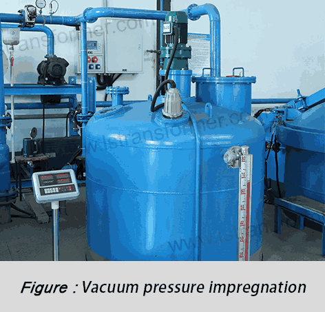
(1) Epoxy-Resin Impregnated Struts:
Glass-fiber-reinforced epoxy (bending strength ≥350 MPa, 4× stronger than wood) reduces radial deformation from 3.2 mm to 0.8 mm.
(2) Axial Compression Systems:
Disk spring assemblies (preload ≥50 kN) mitigate axial compression, increasing withstand cycles from 1 to 3 (per IEC 60076-5).
3.1.2 Performance Comparison:
| Parameter | Traditional | Reinforced |
| Axial Deformation (mm) | 3.2 | 0.8 |
| Short-Circuit Cycles | 1 | 3 |
3.2 Core and Clamping Structure Enhancements
3.2.1 Reinforcement Techniques:
(1) Low-Hysteresis Silicon Steel: 23ZDKH90 steel reduces core vibration energy transfer by 40%, avoiding resonance (ISO 10816-3 compliant).
(2) Multi-Layer Welded Clamps: Q345B steel (yield strength 345 MPa, 47% higher than Q235) absorbs 300 kN axial forces (meets IEEE C57.12.90).
3.2.2 Mechanical Properties:
| Material | Yield Strength (MPa) | Damping Ratio (ξ) |
| Q235 Steel | 235 | 0.02 |
| Q345B Steel | 345 | 0.05 |
In Summary
Conclusion Modern transformers reinforced viaIEC 60076-5 andIEEE C57.12.90 standards can withstand ≥50 kA short-circuit currents (IEC Level 4). Global cases show a 70% reduction in annual failure rates (ABB 2023 Whitepaper). For customized solutions, contact our technical team for simulation, testing, and validation services.
Contact
LuShan, est. 1975, is a Chinese professional manufacturer specializing in power transformers and reactors for 50+ years. Leading products are single-phase transformer, three-phase isolation transformers, electrical transformer, distribution transformer, step down and step up transformer, low voltage transformer, high voltage transformer, control transformer, toroidal transformer, R-core transformer; DC inductors, AC reactors, filtering reactor, line and load reactor, chokes, filtering reactor, and intermediate, high-frequency products.
Our power transformers and reactors are widely used in 10 application areas: rapid transit, construction machinery, renewable energy, intelligent manufacturing, medical equipment, coal mine explosion prevention, excitation system, vacuum sintering(furnace), central air conditioning.
Know more about power transformer and reactor: www.lstransformer.com.
If you would like to obtain customized solutions for transformers or reactors, please contact us.
WhatsApp:+86 13787095096
Email: marketing@hnlsdz.com

