 EN
EN
 FR
FR DE
DE ES
ES
Environmental Adaptability Requirements of Reactors in High-Speed Railway Traction Systems
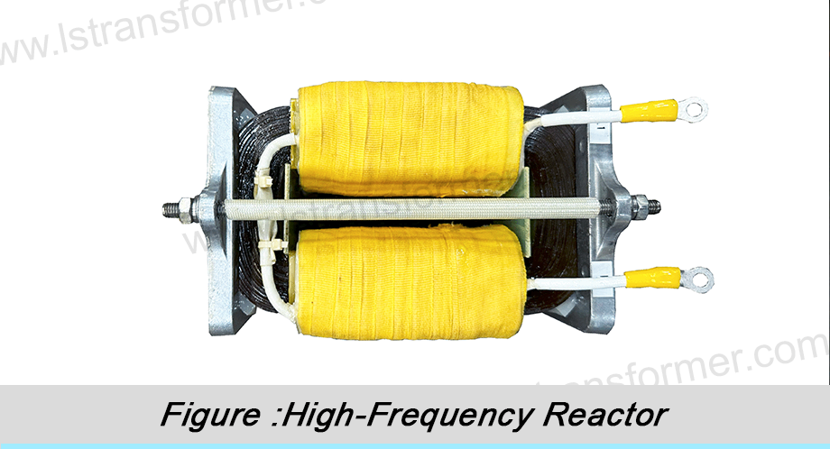
As a core pillar of modern transportation, high-speed rail relies heavily on the stability of its traction system under harsh operating conditions. Reactors, being a critical component of traction converters, directly impact train reliability and safety through their environmental adaptability. This article provides an in‑depth analysis of key environmental adaptability requirements for reactors in high‑speed railway traction systems and the underlying technical principles.
Content
1. Resistance to Extreme Mechanical Vibration and Shock
● Reason:
High‑speed trains operate at speeds of 250–350 km/h, where track irregularities, switches, and aerodynamic disturbances cause intense vibration and shock. Test data show that critical onboard components must withstand random vibrations of at least 5 Grms (frequency range 5–2000 Hz) and transient shocks up to 50 g.
● Key Requirements:
—Fatigue‑resistant structural design:
High‑strength alloy frames combined with multi‑point elastic suspension systems effectively disperse and absorb vibration energy. Critical bolted joints use anti‑loose washers and thread‑locking adhesive to prevent loosening due to micro‑motion wear.
—Winding reinforcement against deformation:
Coils are impregnated using Vacuum Pressure Impregnation (VPI) with tough epoxy resin and interleaved with Nomex® reinforcing material. This process ensures deep resin penetration, forming a monolithic “fiberglass” structure after curing that greatly enhances mechanical strength and natural frequency, avoiding resonance‑induced fractures.
—Magnetic core anti‑shift locking:
Laminated silicon steel sheets use stepped‑lap joints and are compressed under specific pressure (e.g., 15–20 MPa MPa), complemented by high‑temperature adhesive coating. The clamping force is precisely calculated via Finite Element Analysis (FEA), ensuring the core maintains uniform air gaps under vibration, preventing local overheating from flux distortion.
Test Item | Severity Level | Parameter Description | Verification Goal |
Random Vibration (Long./Trans.) | Class 1 | 5–2000 Hz, 5 Grms (4 hours per axis) | Structural integrity, bolt locking |
Functional Shock | Class 1 | Half‑sine wave, 50 g peak, 30 ms pulse width | Transient overload tolerance |
Long‑term Operational Vibration | – | Equivalent line‑measured spectrum, >10⁷ cycles | Fatigue life resistance |
|
Table 1: Typical mechanical environment requirements for high‑speed rail reactors (according to EN 61373 standard)
2. Efficient Thermal Management Across Wide Temperature Ranges
● Reason:
Reactor power losses (copper loss I²R + iron loss) convert into heat, while the confined space and poor cooling conditions in the traction compartment lead to ambient temperatures up to 70 °C in summer. Meanwhile, the reactor’s own temperature rise (ΔT) must be limited to 80 K (per EN 61557), i.e., hot‑spot temperature ≤150 °C (H‑class insulation limit).
● Core Thermal Management Technologies:
Application of Low-Loss Materials: Thin-gauge (0.23 mm) high-permeability silicon steel sheets, such as the JNEH series, are used. Their core loss P<sub>1.7/50</sub> is ≤ 0.98 W/kg. The eddy current loss formula

(K<sub>e</sub>: material constant, t: sheet thickness) shows that reducing the thickness t by 50% decreases eddy current losses by 75%.
Optimization of Forced Air Cooling System: An axial–radial composite air duct is designed, with computational fluid dynamics (CFD) simulations used to determine the optimal deflector angle (e.g., a 30° inclination). The air-cooling system must maintain a winding surface wind speed of ≥ 2 m/s and ensure a convective heat transfer coefficient h > 50 W/(m²·K), even at an intake air temperature of 70°C.
Enhanced Thermal Conductivity Through Vacuum Impregnation:The vacuum pressure impregnation (VPI) process utilizes high thermal conductivity epoxy resin (λ ≥ 0.8 W/m·K) to fill microscopic gaps within the coils. According to Fourier's law

the cured resin forms a continuous heat conduction path, increasing the overall thermal conductivity of the winding bymorethan 30% compared to traditional processes.
3. Strong Electromagnetic Compatibility (EMC) and Anti‑Interference Performance
● Reason:
Traction converters operate at kHz‑level switching frequencies (e.g., IGBT at 2–5 kHz kHz), with di/dt reaching thousands of A/µs, generating strong electromagnetic fields around the reactor. Unsuppressed electromagnetic noise (EMI) can interfere with train signaling systems (e.g., ATP’s 1750 MHz wireless communication).
● Key EMC Design Points:
Low Stray Capacitance Structure:
A segmented winding design (e.g., 8-section layer winding) is adopted, with PTFE film (εᵣ ≈ 2.1) inserted between layers. The capacitance calculation formula

indicates that reducing the dielectric constant εᵣ and area A while increasing the interlayer distance d can lower the distributed capacitance to 1/5 of that in conventional structures, thereby suppressing high-frequency oscillations.
Multi-layer Electromagnetic Shielding:
A double-layer shield is applied externally to the reactor: the inner layer consists of a 1 mm thick copper magnetic shield (absorbing low-frequency magnetic fields), while the outer layer is an aluminum electrical shielding shell with a zinc-nickel coating (20 μm) (reflecting high-frequency electric fields). According to the skin depth formula

the nickel-zinc alloy exhibits δ ≈ 22 μm at 1 MHz, attenuating over 90% of radiated noise.
Grounding and Filtering System:
All shielding layers are connected to the converter’s main grounding bus via low-impedance grounding straps (< 2.5 mΩ), and an RC damping circuit (e.g., 10 Ω + 100 nF) is installed at the coil input to suppress voltage spikes and resonant overvoltages.
4. Tolerance to High Altitude and Polluted Environments
● Reason:
High‑speed rail lines often traverse regions above 2000 m altitude (e.g., Qinghai–Tibet Railway), where air density is only 75% of sea level, reducing heat dissipation capability by about 20%. Additionally, contaminants like dust and salt fog can cause tracking on the reactor’s external insulation surface.
● Adaptation Solutions:
—Altitude derating design:
According to IEC 60664, insulation strength decreases by about 10% per 1000 m altitude increase. Designs incorporate a 20% insulation margin (e.g., plateau‑type products have power‑frequency withstand voltage raised to 12 kV), and corona‑resistant polyimide film (e.g., Kapton® CR) is used to strengthen interlayer insulation.
—Anti‑pollution flashover coating process:
Room Temperature Vulcanizing (RTV) silicone rubber is sprayed on the reactor’s external insulation surface, providing a hydrophobic contact angle >105°. When salt fog particles adhere, the RTV coating forms a hydrophobic film via molecular chain migration, breaking continuous water films into isolated droplets and blocking leakage paths (tests show CTI values can be increased to 600 V).
—Anti‑condensation heating device:
A self‑regulating PTC heater (power density 0.5 W/cm²) is integrated into the reactor base. Activated automatically when humidity sensors detect RH >85%, it maintains the surface temperature at least 5 °C above the dew point, preventing surface discharge due to moisture absorption.
Environmental Threat | Physical Impact | Protective Measures | Verification Standard |
Low Air Pressure (3000 m alt.) | Insulation strength ↓20% | External clearance ↑25%, withstand voltage ↑20% | IEC 60076‑15 |
Salt Fog Corrosion (Coastal) | Metal corrosion, insulation surface conductivity ↑ | IP55 enclosure protection, nickel‑plated copper parts | ISO 9227 Salt Spray Test |
Dust Accumulation (Desert) | Heatsink clogging, temperature rise ↑15 K | Dust filter + periodic blowing design | IEC 60529 Dust Test |
Table 2: Protective measures for reactors in high‑altitude and polluted environments
5. Wide‑Frequency‑Range Impedance Stability
● Reason:
Modern traction systems use multi‑level topologies (e.g., 3L‑NPC) with complex output harmonic spectra (including ±1st, ±2nd sidebands of the switching frequency). If the reactor’s impedance fluctuates >±15% within the 1–10 kHz band, filtering failure or even resonance may occur.
● Frequency‑Stabilization Technical Principles:
—Distributed air gap core:
Non‑magnetic spacers (e.g., ceramic) are precisely inserted into the core laminations to distribute air gaps uniformly. Total magnetic reluctance shows that distributed air gaps reduce fringing flux effects at gap edges, ensuring inductance L linearity across the frequency range.
—High‑frequency eddy current suppression:
Litz wire consisting of multiple strands (diameter ≤0.3 mm) with individually insulated strands is used. The eddy current loss formula indicates that reducing wire diameter d by 50% lowers high‑frequency losses to 1/16, maintaining high Q‑factor (>100) even at 10 kHz.
—Thermal deformation compensation:
Negative expansion alloy (e.g., Invar alloy, CTE ≈1.5×10⁻⁶/K) is embedded in the winding former. As temperature rises from -40 °C to 125 °C, the alloy contracts to offset epoxy resin expansion (CTE ≈50×10⁻⁶/K), keeping inductance deviation within ±5%.
Conclusion
The environmental adaptability of traction reactors in high‑speed railways represents a deep integration of materials science, structural mechanics, and electromagnetics. From alloy frames designed for shock resistance, to nano‑shield coatings optimized for EMC, to intelligent thermal management systems adaptable from -40 °C to 70 °C — each link requires precise design through multi‑physics collaborative simulation (e.g., ANSYS Maxwell + Fluent).
Global standards (e.g., EN 50155 for railway electronic equipment, IEC 60076 for power transformers) provide the baseline framework for reactor environmental adaptability. Leading manufacturers are continuously enhancing product service life under extreme conditions (targeting >300,000 km maintenance‑free) through innovative materials (SiC‑Al composite heat sinks), smart operation & maintenance (IoT‑based temperature/vibration monitoring), and digital twin technology.
What special environmental challenges does your high‑speed rail project face? Contact our engineering team for customized reactor environmental adaptability solutions and EN/IEC compliance reports.
Contact Us
LuShan, est.1975, is a Chinese professional manufacturer specializing in power transformers and reactors for50+ years. Leading products are single-phase transformer, three-phase isolation transformers,electrical transformer,distribution transformer, step down and step up transformer, low voltage transformer, high voltage transformer, control transformer, toroidal transformer, R-core transformer;DC inductors, AC reactors, filtering reactor, line and load reactor, chokes, filtering reactor, and intermediate,high-frequency products.
Our power transformers and reactors are widely used in 10 application areas: rapid transit, construction machinery, renewable energy, intelligent manufacturing, medical equipment, coal mine explosion prevention , excitation system, vacuum sintering(furnace), central air conditioning.
Know more about power transformer and reactor :www.lstransformer.com.
If you would like to obtain customized solutions for transformers or reactors, please contact us.
WhatsApp:+86 13787095096
Email:[email protected]