
 EN
EN
 FR
FR DE
DE ES
ES
What Are the Environmental Requirements for Transformers in Urban Underground Substations?
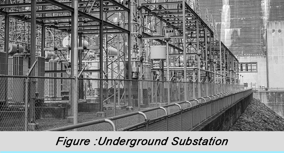
With the acceleration of urbanization and increasingly scarce land resources, underground substations have become a vital component of modern urban power infrastructure. As the core equipment of substations, transformers face numerous special challenges when installed and operating in underground environments. This article explores in detail the key environmental requirements for transformer installation in urban underground substations, aiding power planners, engineers, and maintenance personnel in better understanding these specialized technical specifications.
Content
1. Temperature and Ventilation Control Requirements
The most significant environmental characteristic of an underground substation is its enclosed nature, which poses severe challenges for transformer heat dissipation. Unlike above-ground substations, the underground environment lacks natural convection, allowing heat to accumulate easily. This can lead to transformer overheating, subsequently affecting insulation performance and service life.
Temperature control measures must include:
● Forced Ventilation Systems:
Utilize mechanical ventilation systems composed of axial fans and ducts. According to IEEE Std C57.91-2011 recommendations, maintain the ambient temperature below 40°C.
Ventilation air volume calculation follows the formula:
Q = H / (ρ ×Cp× ΔT)
Where Q is the required air volume (m³/s)
H is the total transformer loss (W)
ρ is the air density (approx. 1.2 kg/m³)
Cp is the specific heat capacity of air (approx. 1005 J/kg·K)
ΔT is the allowable temperature rise (typically taken as 15 K)
● Air Conditioning Refrigeration Systems:
When ventilation alone is insufficient, dedicated air conditioning units are required. The cooling capacity should meet the heat generation at the transformer's maximum load, considering redundant design.
● Temperature Monitoring Network:
Deploy multiple temperature sensors around the transformer for real-time monitoring of hot spot temperatures, ensuring compliance with IEC 60076-7 standard requirements.
Transformer Capacity (kVA) | Minimum Ventilation (m³/h) | Recommended Ventilation Method | Temperature Control Standard |
≤ 1000 | 1500 - 3000 | Natural + Axial Fan | ≤ 40°C |
1000 - 5000 | 3000 - 8000 | Mechanical Forced Ventilation | ≤ 38°C |
≥ 5000 | ≥ 10000 | Mechanical + AC Assist | ≤ 35°C |
Table 1: Requirements for Ventilation Systems by Different Capacity Transformers
2. Humidity, Waterproofing, and Moisture Protection Requirements
The relative humidity in underground environments is usually higher than above ground, especially during rainy seasons or in areas with high water tables. High humidity reduces transformer insulation performance and accelerates metal component corrosion, making humidity control crucial.
The waterproofing and moisture protection system should include:
● Anti-seepage Wall Design:
Use reinforced concrete structures with added waterproofing agents. The permeability coefficient should be less than 1×10⁻¹¹ m/s. Wall thickness is typically not less than 300mm, with water stops installed.
● Drainage System:
Sump capacity should accommodate the maximum possible inflow over 24 hours, equipped with a dual-pump system (one operational, one standby). Drainage pump flow rate is calculated by Q = CA√(2gh), where C is the flow coefficient (approx. 0.6), A is the outlet cross-sectional area, g is gravitational acceleration, and h is the head height.
● Dehumidification Equipment:
Maintain relative humidity below 60% (IEEE Std 979 recommended value). Dehumidification capacity calculation: W = V × ρ × (ω₁ - ω₂), where V is space volume, ρ is air density, ω₁ and ω₂ are the initial and target moisture contents respectively.
● Sealing Treatment:
Use specialized sealant on transformer bushings, terminals, etc., meeting the IP68 waterproof rating specified in IEC 60840 standard.
3. Spatial Layout and Installation Requirements (In-depth Optimized Version)
Space constraints in underground substations present unique challenges for transformer installation, requiring comprehensive consideration from perspectives like 3D space utilization, equipment interaction, and lifecycle management.
(1)Principles of Three-Dimensional Space Planning
Depth design considerations:
● Vertical Layering:
Typically adopt a three-layer structure: "Cable Layer - Equipment Layer - Ventilation Layer". The transformer should be placed in the middle of the equipment layer, with a height ≥ 2.5m from the base plate (per IEEE Std 841), and reserve ≥ 1.2m overhead clearance for maintenance. This layout ensures equipment stability and facilitates cable connection and maintenance work.
● Horizontal Zoning:
Divide into functional areas: Core Equipment Zone, Auxiliary Equipment Zone, and Access Corridor Zone. Place the transformer body in the core zone, maintaining a distance D from the nearest wall ≥ max(1.5m, 0.3 × Equipment Height). This distance is based on thermal radiation calculationq = εσ(T₁⁴ - T₂⁴), where ε is the emissivity (0.9 for transformers), σ is the Stefan-Boltzmann constant (5.67×10⁻⁸ W/m²K⁴).
(2)Dynamic Installation Engineering
Key points for transport and installation system design:
● Sliding Track System:
Use heavy-duty roller guides with load capacityW = μN + mg(sinθ + μcosθ), where μ is the friction coefficient (0.15 for steel-on-steel), θ is the inclination angle (should be < 5°). Install hydraulic buffers at track ends, with absorbed energy E = 0.5mv² ≤ Ed (where Ed is the rated absorbed energy).
● 3D Positioning Technology:
Use laser alignment instruments to ensure installation accuracy: levelness deviation ≤ 1mm/m (per IEC 61936), centerline deviation ≤ 3mm. Positioning error Δx = √(Δx₁² + Δx₂²), where Δx₁ is manufacturing tolerance, Δx₂ is installation error.
Parameter | ≤10 MVA | 10-40 MVA | ≥40 MVA | Test Standard |
Foundation Bearing (MPa) | 0.8 | 1.2 | 1.5 | GB50007 |
Vibration Displacement (mm) | ≤ 0.05 | ≤ 0.03 | ≤ 0.02 | ISO10816 |
Positioning Accuracy (mm) | ±5 | ±3 | ±2 | IEC60076 |
Lifting Point Safety Factor | 3.5 | 4.0 | 4.5 | ASME B30.20 |
Table 2: Spatial Parameter Specifications for Transformers of Different Capacities
(4)Maintenance Accessibility Design
Full lifecycle maintenance plans should include:
● Modular Disassembly Interfaces:
Flange connection bolt spacing determined byP = πD / n, where D is the flange diameter, n is a multiple of 4 (minimum 16). Preload forceF = 0.7 × σy × As, where σy is the bolt yield strength, As is the stress cross-sectional area.
● Visual Inspection Walkways:
Install peripheral corridors with widthW = 0.8 + 0.1 × Equipment Height (m), floor load ≥ 5 kN/m². The viewing angle α for key monitoring points (bushings, oil gauges, etc.) should satisfy tanα = h / d ≥ 0.7 (h is eye height, d is horizontal distance).
4. Fire Safety and Security Requirements (Systematically Upgraded Version)
Fire protection design for underground substations needs to establish a four-level "Prevention-Control-Containment-Extinguishment" protection system, forming a defense-in-depth.
(1)Fire Dynamics Protection
Key technologies for thermal hazard prevention and control:
● Oil Pool Fire Suppression System:
For oil-immersed transformers, use intumescent fire-resistant coatings with expansion ratio K = V₂ / V₁ ≥ 30 (V₂ is post-expansion volume). Coating thickness δ = Q / (λ × ΔT), where Q is the heat flux (take 50 kW/m²), λ is the thermal conductivity (≤ 0.1 W/m·K after expansion).
● Smoke Management:
Smoke exhaust volume Q_smoke = 0.19 P √H, where P is the fire compartment perimeter compartment perimeter (m), H is the height (m). Smoke vent velocity should be 6-8 m/s, ensuring smoke layer height remains above 2m (NFPA92 standard).
(2)Multi-level Linked Protection
Intelligent Fire Protection System Architecture:
● Detection Layer:
Triple-wavelength flame detectors (response wavelengths <3μm, 3-5μm, >5μm), with placement density increased by 30% compared to above-ground.
● Control Layer:
Adopt PES controllers (Performance-based Engineering Safety), with failure rate λ ≤ 1×10⁻⁶ /h.
● Execution Layer:
Combined valve group response time t = V / (Q × C), where V is pipe volume, Q is flow rate, C is the medium coefficient (1.2 for gas).
(3)Structural Fire Protection
Specific requirements for fire-resistant construction:
● Concrete Protective Layer:
Thickness calculated by R = 0.1 × √(t / k), where t is fire resistance time (min), k is the conduction coefficient (0.0015 for concrete). Reinforcement cover ≥ 50mm, add polypropylene fibers (dosage 0.9 kg/m³) to prevent spalling.
● Fire Sealing:
Use composite fire barrier wraps, expansion pressureP = ηRT / V(η is number of moles of gas, R is the constant). Must withstand pressure ≤ 50 kPa during a 3-hour fire resistance test.
Material Type | Thermal Conductivity (W/m·K) | Expansion Ratio | Suitable Temperature | Certification Standard |
Calcium Silicate Board | 0.15 | None | ≤ 1000°C | UL263 |
Expanded Graphite | 0.08 | 100x | ≤ 800°C | EN1366 |
Aerogel Blanket | 0.02 | None | ≤ 650°C | ISO834 |
Ceramic Fiber | 0.12 | None | ≤ 1260°C | ASTM E119 |
Table 3: Performance Comparison of Fire-Resistant Materials
5. Electromagnetic Compatibility and Noise Control (Deepened Implementation Plan)
The semi-enclosed nature of the underground environment causes electromagnetic interference and noise issues to exhibit standing wave effects, requiring targeted measures.
(1)Electromagnetic Topology Optimization
Methods for building a 3D shielding system:
● Layered Shielding:
Outer layer uses 1mm galvanized steel sheet (shielding effectiveness ≥ 40 dB @ 1 MHz), inner layer uses 0.3mm copper foil (≥ 60 dB). Use EMI gaskets at joints, transfer impedance Zt < 5 mΩ/m (IEC 61000-5-7).
● Waveguide Filtering:
Design vents as cutoff waveguides, diameter d < c / (2f √εr), where c is the speed of light, f is the highest interference frequency, εr is the dielectric constant. Typical size: honeycomb structure aperture ≤ 5mm, depth ≥ 50mm.
(2)Vibration Transmission Control
Multi-stage Vibration Isolation System Design:
● Primary Isolation:
Rubber isolator stiffness k = (2πf)²m, f is the disturbance frequency (typically 100 Hz for transformers), m is the mass. Damping ratio ζ = c / (2√(km)) takes 0.05 - 0.1.
● Secondary Isolation:
Adopt active electromagnetic suspension systems, control bandwidth Δf ≥ 2 × Speed fluctuation range, actuation force F = ma, a is the allowable vibration acceleration (take 0.1g for underground stations).
(3)Acoustic Black Hole Effect
Application of Nonlinear Sound Absorption Structures:
● Graded Impedance Materials:
Acoustic impedance Z(x) = Z₀ e^(βx), β is the attenuation coefficient (take 0.5 - 1.5 Np/m). Placing graded porous material with thickness ≥ 100mm at 1m from the transformer can reduce noise above 500Hz by 15 dB(A).
● Active Noise Cancellation Systems:
Error microphone placement follows the λ/4 principle (λ is wavelength), control algorithm uses FxLMS, convergence coefficient μ = 0.0001 / (P × L), P is input power, L is filter length.
(4)Harmonic Mitigation Matrix
Multidimensional Filtering Solutions:
● Spatial Filtering:
Configure zero-sequence filters with delta connection, impedance ratio Z₀ / Z₁ ≥ 10, where Z₀ = 3R + 3X, Z₁ = R + jX.
● Temporal Filtering:
Active filter switching frequency f_sw ≥ 10 × Highest harmonic order, current tracking error δ = √(∑(I_h - I_href)²) / I₁ ≤ 5% (IEC 61000-3-6).
Through the in-depth optimization measures described above, the electromagnetic disturbance level of transformers in underground substations can meet CISPR11 Class A requirements, with noise controlled below 55 dB(A) (measured 1m from equipment), fully achieving the IEEE Std 1127 recommended values.
International Standards and Best Practices
Major global standard systems have different focuses regarding underground substation transformer installation:
• IEC Standards (International Electrotechnical Commission): Emphasize equipment performance and testing methods, e.g., IEC 60076 series.
• IEEE Standards (Institute of Electrical and Electronics Engineers): Focus on system design and safety, e.g., IEEE Std C57 series.
• GB Standards (Chinese National Standards): Adapted to national conditions, e.g., GB/T 17468-2019.
Conclusion
The environmental requirements for transformer installation in urban underground substations constitute a complex issue involving multiple factors across disciplines such as thermodynamics, structural engineering, and electrical safety. With technological advancements, new materials(e.g., nanofluid insulating oil)and intelligent monitoring technologies are continuously improving the reliability and efficiency of underground substations. Planners and engineers need to find the optimal balance between initial investment and long-term operational costs, spatial constraints and safety margins, and technical advancement versus mature reliability to ensure these "Urban Power Hearts" operate safely and efficiently within the underground environment.
Contact Us
LuShan, est.1975, is a Chinese professional manufacturer specializing in power transformers and reactors for50+years. Leading products aresingle-phase transformer, three-phaseisolationtransformers,electrical transformer,distribution transformer, step down and step up transformer, low voltage transformer, high voltage transformer, control transformer, toroidal transformer, R-core transformer;DC inductors, AC reactors, filtering reactor, line and load reactor, chokes, filtering reactor, and intermediate,high-frequency products.
Our powertransformers and reactors are widely used in 10 application areas: rapid transit, construction machinery, renewable energy, intelligent manufacturing, medical equipment, coal mine explosion prevention , excitation system, vacuum sintering(furnace), central air conditioning.
Know more about power transformer and reactor :www.lstransformer.com.
If you would like to obtain customized solutions for transformers or reactors, please contact us.
WhatsApp:+8613787095096
Email:[email protected]