
 EN
EN
 FR
FR DE
DE ES
ES
What Special Environmental Factors Should Be Considered for Reactors in Marine Applications?
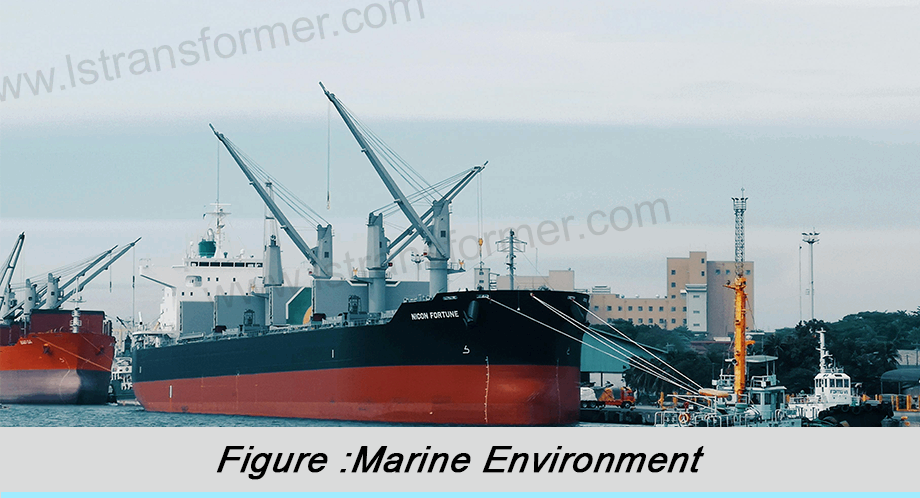
The ship power system is a core component of modern vessels, and reactors, as indispensable elements within these systems, face unique challenges in marine applications. Compared to land-based environments, the operational setting of a ship is much harsher. Special factors such as salt spray corrosion, continuous vibration, and space constraints must be considered.
This article will delve into the environmental factors that require special attention for reactors used in marine applications. It analyzes how these factors affect reactor performance and provides corresponding solutions. By understanding these key factors, ship designers and electrical engineers can select more suitable reactor products, ensuring the reliability and safety of the vessel's power system while meeting relevant standards from the International Maritime Organization (IMO) and the International Electrotechnical Commission (IEC).
Content
1. Impact of the Marine Corrosive Environment on Reactors and Protective Measures
The high salinity and humid air in the marine environment are primary challenges for reactors. Chloride ions in salt spray possess strong penetrative and corrosive properties, capable of damaging the protective layers on metal components of reactors, leading to material degradation. Research indicates that in marine environments, the corrosion rate of ordinary carbon steel can be 4-5 times higher than in inland environments.
(1)Corrosion Mechanism Analysis:
Salt spray corrosion is an electrochemical process. When salt spray deposits on metal surfaces, forming an electrolyte film, it triggers anodic oxidation and cathodic reduction reactions. For reactors, this corrosion primarily occurs at the following key locations:
•Winding conductors (especially at joints and connection points)
•Iron core laminations
•Enclosures and structural supports
•Cooling system components
(2)Protective Measures:
●Material Selection:
Using materials with excellent corrosion resistance is a fundamental solution. For winding conductors, tin-plated copper wire or nickel alloy conductors can be used; enclosures should preferably be made of 316L stainless steel or aluminum-magnesium alloy; fasteners should use A4-80 grade stainless steel. Table 1 compares the salt spray corrosion resistance of different materials.
Material Type | Salt Spray Test Time (h) | Corrosion Level | Suitable Application | Cost Index |
Ordinary Carbon Steel | 96 | Severe Corrosion | Not Recommended | 1.0 |
Galvanized Steel | 480 | Moderate Corrosion | Non-critical structural parts | 1.2 |
304 Stainless Steel | 1000 | Slight Corrosion | General enclosures | 2.5 |
316L Stainless Steel | 2000 | Very Slight Corrosion | Critical components | 3.0 |
Aluminum-Magnesium Alloy | 1500 | Slight Corrosion | Enclosures / Heat Sinks |
Table 1: Comparison of Corrosion Resistance of Different Materials in Marine Environments
●Surface Treatment Technology:
For parts where ordinary steel must be used, a triple-protection system can be applied: phosphate coating base layer (enhances adhesion), epoxy zinc yellow primer middle layer (cathodic protection), and polyurethane topcoat (barrier protection). This treatment can extend the protective life to over 10 years.
●Sealing Design:
Use enclosure designs with IP66 or higher protection ratings, utilize silicone rubber seals at key points, and employ potting processes for terminal boxes. Additionally, design reasonable drainage structures to prevent water accumulation.
These protective measures significantly increase the service life of reactors in marine environments by blocking corrosion paths, providing sacrificial anode protection, or establishing physical barriers. Practical applications show that optimized marine reactors can last 3-5 times longer than standard products under the same conditions.
2. Impact of Ship Vibration and Mechanical Stress on Reactors and Solutions
Continuous vibration and shock generated during ship operation are the second major challenge for reactors. These mechanical stresses primarily originate from main engine operation, wave impact, and equipment start-stop cycles, potentially causing issues like winding loosening, insulation wear, and fatigue fracture of connectors.
(1)Vibration Characteristic Analysis: Ship vibration can be categorized into three types:
•Low-frequency vibration (1-30Hz): Mainly caused by unbalanced forces from the main engine and propeller, with relatively large amplitude.
•Mid-frequency vibration (30-100Hz): Generated by auxiliary machinery such as pumps and fans.
•High-frequency vibration (>100Hz): Stems from generator electromagnetic forces and gear meshing.
According to ISO 6954 standards, marine equipment should withstand continuous vibration of 2-100Hz frequency and 2-7 m/s² acceleration, as well as shock accelerations of 50-100 m/s².
(2)Structural Dynamics Solutions:
●Anti-Vibration Design Principles:
•–Natural Frequency Avoidance:Optimize the structure through finite element analysis so that the reactor's natural frequencies avoid the main excitation frequency range (typically designed to be >150Hz).
•–Vibration Energy Dissipation: Incorporate high-damping materials like butyl rubber at core clamping points and winding supports.
•–Stress Uniform Distribution:Adopt toroidal winding structures and symmetrical magnetic circuit designs to avoid local stress concentration.
●Key Reinforcement Measures:
•–"Sandwich" Compression Structure for Windings:Pre-compression force is calculated as follows:
F = k×(ε ×E×A)
Where:
F: Required clamping force (N)
k: Safety factor (usually 1.2-1.5)
ε: Insulation material compression ratio (%)
E: Insulation material elastic modulus (Pa)
A: Compression area (m²)
•–Multi-Stage Binding Process for Iron Core:Use fiberglass tape with 300-500N tension for cross-binding, with binding spacing not exceeding 50mm.
•–Use Shock Absorbers for Mounting Base:Select three-directional equal-stiffness shock absorbers. Stiffness calculation must satisfy:
K = (2πf)² ×m
Where f is the main ship vibration frequency and m is the reactor mass.
●Connection Reliability Assurance:
•–Dual Fixation for Electrical Connections:Bolt connection plus welding or brazing.
•–Flexible Connections Flexible Connections for Leads:Allow 10-15% extra length, with bending radius greater than 6 times the conductor diameter.
•–Regular Tightening Checks:Set up removable inspection windows for easy checking of internal fastening status.
Practical applications show that reactors designed with optimized anti-vibration features can reduce vibration-induced failure rates by over 80%, meeting the vibration test requirements of classification societies like DNV GL and ABS.
3. Balanced Design for Ship Space Constraints and Thermal Dissipation Challenges
Ship space is extremely valuable. Reactors must achieve a compact design without compromising without compromising performance, which presents significant challenges for heat dissipation. Furthermore, ambient temperatures on ships can reach 45-55°C, further exacerbating cooling difficulties.
(1)Thermal Design Challenge Analysis: Reactor temperature rise mainly comes from:
•Winding I²R losses
•Core eddy current losses
•Stray losses
In confined spaces, the efficiency of traditional convective cooling drops significantly, potentially causing hot spot temperatures to exceed the allowable limits of insulation materials (typically Class 130-155°C).
(2)Compact Thermal Management Solutions:
●3D Thermal Simulation Optimization:
Use Computational Fluid Dynamics (CFD) methods to establish thermal models, solving the energy conservation equation:
ρc_p∂T/∂t +∇·(-k∇T) = Q
Where:
• ρ: Material density (kg/m³)
• c_p: Specific heat capacity (J/(kg·K))
• k: Thermal conductivity (W/(m·K))
• Q: Heat source term (W/m³)
Simulation can optimize parameters like cooling fin arrangement, airflow duct design, and coolant flow velocity.
●Selection of Efficient Cooling Technologies Cooling Technologies:
Cooling Method | Heat Dissipation Capacity (W/m³·K) | Space Requirement | Maintenance Difficulty | Suitable Power Range |
Natural Air Cooling | 5-10 | Large | Low | <50 kVA |
Forced Air Cooling | 15-30 | Medium | Medium | 50-500 kVA |
Water Cooling | 50-100 | Small | High | >500 kVA |
Phase Change Cooling | 20-40 | Medium | Medium | 100-1000 kVA |
Table 2: Performance Comparison of Different Cooling Methods in Marine Environments
•Ships commonly use hybrid solutions combining forced air cooling and seawater cooling:
––Primary side: Internal air circulation, transferring heat out via heat pipes.
––Secondary side: Seawater-cooled plate heat exchanger, using titanium alloy for corrosion resistance corrosion resistance.
––Temperature Control: Install bimetal automatic regulating valves to control cooling water flow.
●Material and Process Innovation:
•–Use High Thermal Conductivity Insulation Materials:Such as nano-filled epoxy resin, with thermal conductivity thermal conductivity up to 0.8-1.2 W/(m·K).
•–Winding Transposition Technology:Reduces eddy current losses. Effectiveness can be evaluated using the loss calculation formula:
P_eddy = K×f² ×B² ×t² ×V
Where:
· K: Material constant
· f: Frequency (Hz)
· B: Magnetic flux density (T)
· t: Conductor thickness (m)
· V: Conductor volume (m³)
Practice proves that comprehensively applying these measures can reduce the temperature rise of compact marine reactors by 20-30K, ensuring service life while reducing volume by 40%.
4. Requirements for Reactors from Special Conditions in Ship Power Systems
Ship power systems are characterized by large voltage fluctuations, high harmonic content, and strong short-circuit capabilities. These special operating conditions operating conditions place higher demands on reactors.
(1)System Characteristic Analysis:
•Voltage fluctuation range:According to IEC 60092-501, marine systems allow voltage fluctuations of ±10% (transient up to ±20%).
•Frequency fluctuation:Steady-state ±5%, transient ±10%.
•Harmonic distortion rate:THDv can reach 8-15%, with significant 5th and 7th harmonics present.
•Short-circuit current:Can reach 10-15 times the rated current.
(2)Reactor Adaptation Design:
●Overload Capacity Design:
•–Thermal Time Constant Optimization Constant Optimization:Balance heat capacity and dissipation characteristics so the reactor can withstand short-term overloads. The thermal time constant τ is calculated as:
τ= C/R
C is heat capacity (J/K)
R is thermal resistance (K/W)
•–Material Temperature Margin:Select Class H (180°C) insulation materials insulation materials, operating at 130°C, leaving ample margin.
●Harmonic Countermeasures:
•–Frequency Response Design:Ensure stable impedance characteristics from characteristics from fundamental frequency up to the 25th harmonic.
–Additional Loss Control:Use Litz wire or subdivided conductors to reduce skin effect. Skin depth δ is calculated as follows:
δ=√(ρ/(πμf))
*Where:
ρ: Resistivity (Ω·m)
μ: Permeability (H/m)
f: Frequency (Hz)*
●Short-Circuit Withstand Capability:
•Mechanical Strength Calculation:Verify the stability of windings under short-circuit electromagnetic forces. Electromagnetic force F is calculated as:
F = B×I×L
Where B is magnetic flux density (T), I is current (A), L is conductor length (m).
•Thermal Shock Test:Perform short-circuit tests according to IEC 60076-6, verifying that the instantaneous temperature rise does not exceed 250K.
●System Compatibility:
•–Impedance Matching:Reactance value design must consider generator transient reactance and cable parameters to avoid resonance.
•–Protection Coordination:Install temperature sensors and current transformers, integrating with the ship management system.
These designs enable reactors to adapt to the demanding requirements of marine power systems, ensuring stable operation under various conditions and reducing failures caused by power quality issues.
Conclusion
The marine application environment poses comprehensive challenges for reactors, ranging from corrosion protection and mechanical strength to thermal management and system adaptation. Each aspect requires careful design. By adopting corrosion-resistant materials, optimizing anti-vibration structures, innovating cooling solutions, and enhancing electrical performance, modern marine reactors are now well-equipped to meet these special requirements. When selecting reactors, it is recommended to prioritize products complying with international standards like IEC 60076 and IEC 60092, and confirm they hold certifications from major classification societies such as DNV GL, LR, and ABS. As ship power systems evolve towards higher voltages and larger capacities, the performance requirements for reactors will continue to increase, necessitating ongoing innovation from manufacturers to provide users with more reliable and efficient solutions.
Contact Us
LuShan, est.1975, is a Chinese professional manufacturer specializing in power transformers and reactors for50+years. Leading products aresingle-phase transformer, three-phaseisolationtransformers,electrical transformer,distribution transformer, step down and step up transformer, low voltage transformer, high voltage transformer, control transformer, toroidal transformer, R-core transformer;DC inductors, AC reactors, filtering reactor, line and load reactor, chokes, filtering reactor, and intermediate,high-frequency products.
Our powertransformers and reactors are widely used in 10 application areas: rapid transit, construction machinery, renewable energy, intelligent manufacturing, medical equipment, coal mine explosion prevention , excitation system, vacuum sintering(furnace), central air conditioning.
Know more about power transformer and reactor :www.lstransformer.com.
If you would like to obtain customized solutions for transformers or reactors, please contact us.
WhatsApp:+8613787095096
Email:[email protected]