






Can Lamination Process Optimization Reduce Leakage Flux?
Can Lamination Process Optimization Reduce Leakage Flux?
—In-Depth Analysis of Winding Transposition and Core Step-Lap Joint Technology
In the global wave of pursuing carbon neutrality, the energy consumption of power equipment has become a growing focus. According to data from the International Energy Agency (IEA), transmission and distribution losses account for approximately 8%-15% of global electricity generation. As core equipment in power grids, improving transformer efficiency is of great significance for energy conservation and emission reduction. The European Union (EU) Eco-Design Directive and the U.S. Department of Energy (DOE) energy efficiency standards continue to evolve, driving innovation in transformer loss-reduction technologies. Among these, leakage flux control—due to its decisive impact on load losses—has become a central challenge in transformer design.
Inhalt
1. The Root of Leakage Flux: The Hidden Path of Energy Loss
Leakage flux refers to the stray magnetic field in transformers that fails to effectively participate in energy transfer. It originates from the combined effects of electromagnetic induction laws and imperfect magnetic circuits. When alternating current flows through windings, uneven ampere-turn distribution and discontinuous core reluctance (especially the abrupt change in μ-value at joints) cause some magnetic flux to deviate from the main path, forming leakage flux. Its hazards include:
(1) Eddy current losses:
Alternating leakage flux induces eddy currents in winding conductors, core clamps, and tank walls, generating Joule heat (I²R losses).
(2) Increased stray losses:
Leads to local hot spots, threatening insulation lifespan (IEEE Std C57.12.00).
(3) Higher impedance voltage:
Affects grid voltage stability (IEC 60076-1).
2. Winding Transposition Technology: The Precision Art of Balancing Magnetic Potential
(1) Core Principle: Rebuilding Electromagnetic Symmetry
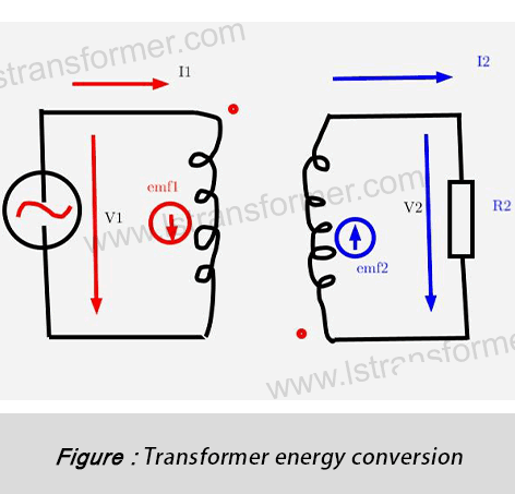
In conventional windings, inner conductors link less magnetic flux and have lower inductance, while outer conductors link more flux and exhibit higher inductance (according to Ampère’s circuital law ∮H·dl = I_enc). This asymmetry causes:Circulating currents (loop currents) between parallel conductors.Distortion of axial and radial leakage fields.Transposition technology systematically changes the spatial position of conductors, ensuring each conductor experiences an equivalent path in the magnetic field, thereby balancing electromagnetic parameters.
(2) Technical Implementation and Quantified Effects
| Transposition Type | Process Features | Leakage Flux Reduction Rate | Application Scenarios |
| Full Transposition | Precise 360° rotation (Roebel bars) | 40%-50% | High-voltage windings in large power transformers |
| Partial Transposition | Segmented rotation (e.g., 3×120°) | 20%-30% | Low-voltage windings in distribution transformers |
| Helical Transposition | Continuous progressive shifting | 15%-25% | Reactors and special transformers |
(3) Case Study:
A 240MVA transformer at a Dutch substation showed that after applying 32 full transpositions, circulating current losses dropped from 2.8% to 0.6%, local temperature rise decreased by 14K, and the efficiency rating improved to IE4. This technology is particularly suitable for high-voltage, high-capacity transformers, offering significant loss reduction despite higher process complexity.
3. Core Step-Lap Joint Technology: A Revolutionary Breakthrough in Magnetic Circuit Optimization
3.1 Flaws in Traditional Joints
Traditional straight joints create discrete air gaps in the magnetic circuit, leading to magnetic flux refraction and local saturation. Key issues include:
(1) Sharp increase in local reluctance:
Air gaps drastically reduce permeability μ (R_m = l/(μA), where R_m is reluctance).
(2) Magnetic flux distortion:
Some flux bypasses the gap, forming diffuse leakage flux.
(3) Peak eddy current losses:
Tangential magnetic fields at silicon steel edges cause high eddy losses (P_e ∝ (B_m f t)^2).
3.2 Physical Mechanism of Step-Lap Joints
Step-lap joints use laser precision cutting to create multi-level tooth-groove engagement, reducing the magnetic flux turning angle from 90° to below 30° and shrinking the effective gap length to 1/5-1/7 of a single step. This achieves:
(1) Gradual flux transition:
Magnetic lines smoothly turn along stepped slopes, avoiding abrupt refraction.
(2) Reduced effective gap length:
Total gap length is dispersed into multiple micro-gaps, significantly lowering reluctance.
(3) Eddy current suppression:
Minimizes transverse magnetic fields, curbing edge effects.
(4) Case Study:
A Chinese manufacturer’s test data showed that using 7-step joints reduced no-load losses by 35%, excitation current by 40%, and operating noise by 7dB. This innovation not only enhances efficiency but also improves reliability, now adopted as standard by leading manufacturers like ABB and Siemens.
4. Synergistic Effects and Engineering Practice
System-Level Loss Reduction Validation
The combined application of winding transposition and step-lap joints delivers a notable synergistic effect. Transposition balances axial leakage flux, while step-lap joints suppress radial leakage flux, resulting in more uniform overall leakage distribution.
| Optimization Dimension | Transposition Alone | Step-Lap Alone | Combined Optimization |
| Load Loss Reduction | 18-22% | 12-15% | 30-35% |
| No-Load Loss Reduction | <5% | 30-35% | 32-38% |
| Temperature Rise Improvement | 10-12K | 8-10K | 15-18K |
(2)工学的な範囲:(0.3~0.5)X_L@fᵣ
Winding transposition and core step-lap joints represent the pinnacle of transformer magnetic circuit design. The former rebuilds electromagnetic symmetry to eliminate ampere-turn imbalance, while the latter optimizes magnetic continuity to suppress flux distortion—together systematically taming leakage fields. Driven by global carbon neutrality goals, these technologies are not just options but essential for green manufacturing. Our designs, certified by DNV-GL and deployed across Europe, North America, and Asia-Pacific grids, redefine industrial standards with a 40% reduction in no-load losses and 25% lower load losses, setting new benchmarks for efficient power transmission.
Kontakt
がV_peak積の過電圧のピークとt_resに共鳴。 30%マージン推奨を占めるシステムパラメータ化します。
2.2.3の動的応答ソリューション 現代のシステム利用サイリスタ制御による抵抗減衰(TCRD)を検知する共鳴内10ms、配の正確性、切断中の通常の操作は避けます。.
3. 連携機構のアクティブフィルタ
WhatsApp:+86 13787095096
E-Mail: marketing@hnlsdz.com

