






What Environmental Challenges Do Reactors Face in Photovoltaic Power Stations? — In-Depth Analysis and Solutions
Reactors play a critical role in reactive power compensation, harmonic suppression, and system protection within photovoltaic (PV) power stations. However, since PV plants are often built in open areas with high temperatures, dust, or high altitude, reactors face more severe environmental challenges compared to traditional grid applications. This article provides a detailed analysis of five major environmental issues that reactors may encounter in PV power plants and offers practical solutions covering technical selection, operational optimization, and monitoring strategies to ensure long-term stable operation.
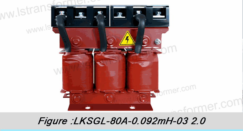
![]() 1. Impact of High Temperature on Reactors & Solutions
1. Impact of High Temperature on Reactors & Solutions
![]() 1.1 Problem Analysis
1.1 Problem Analysis
PV power stations are typically located in regions with strong direct sunlight, where ambient temperatures can exceed 50°C. Additionally, reactors generate heat during operation (due to copper and iron losses). According toIEC 60076-6,reactors can operate continuously at up to 40°C ambient temperature. Beyond this limit, the following risks arise:
(1) Accelerated insulation aging (lifespan halves with every 8–10°C increase)
(2) Increased winding resistance (higher copper loss, reduced efficiency)
(3) Risk of magnetic core saturation (affects inductance stability)
![]() 1.2 Detailed Solutions
1.2 Detailed Solutions
![]() 1.2.1 Enhanced Cooling Design
1.2.1 Enhanced Cooling Design
(1) Forced Air Cooling System:
Install IP55-rated axial fans inside reactor cabinets (wind speed ≥3 m/s), reducing internal temperature by 15–20°C. Forced convection improves cooling efficiency by 60–70% compared to natural cooling. Fans should include a thermal control switch (set to activate at 50°C).
(2) Optimized Heat Sinks:
Use aluminum fins with 30% more surface area and apply high-emissivity coatings (e.g., anodizing) to improve heat radiation.
![]() 1.2.2 Material Upgrades
1.2.2 Material Upgrades
(1) Utilize Class H (180°C) or higher-grade insulation materials such as Nomex® or mica tape, offering 40% better heat resistance than standard Class B (130°C) insulation.
(2) Implement low-loss silicon steel sheets (e.g., 23ZH100), reducing iron losses by 15–20%.
![]() 1.2.3 Installation Optimization
1.2.3 Installation Optimization
(1) Sunshade Installation: Install ventilated sunshades above reactors (at least 50 cm above the device), lowering surface temperature by 10–15°C.
(2) Avoid Enclosed Spaces: Ensure at least 1-meter clearance for heat dissipation if installed in containerized inverter rooms, and incorporate louvered vents (open area ratio≥30%).
![]() 1.2.4 Smart Monitoring
1.2.4 Smart Monitoring
Integrate PT100 temperature sensors for real-time winding temperature monitoring. Configure SCADA systems with three-level alarms: warning at 70°C, derating at 90°C, and trip at 110°C.
![]() 2. Dust and Contaminant Accumulation & Solutions
2. Dust and Contaminant Accumulation & Solutions
![]() 2.1 Problem Analysis
2.1 Problem Analysis
Arid regions commonly experience dust accumulation on reactor surfaces, forming an insulating layer that reduces heat dissipation efficiency. Tests show that 1 mm of dust can decrease cooling performance by 20–30%. Conductive dust can also cause tracking; IEEE Std 1313.2 defines minimum creepage distance requirements based on pollution levels.
Comparison Table of Pollutant Effects:
| Type of Contaminant | Conductivity | Impact on Heat Dissipation | Typical Regions |
| Ordinary Dust | Niedrig | Medium-High | Desert Areas |
| Industrial Dust | Medium-High | Medium | Near Industrial Zones |
| Salt Mist | Hoch | Niedrig | Coastal Areas |
| Agricultural Dust | Medium | Hoch | Farmland Surroundings |
![]() 2.2 Detailed Solutions
2.2 Detailed Solutions
![]() 2.2.1 Enclosure Protection Enhancement Protection Enhancement
2.2.1 Enclosure Protection Enhancement Protection Enhancement
(1) IP54/IP55 Protection Rating: Use fully sealed reactor enclosures with removable dust filters (mesh count≥60) at air inlets.
(2) Anti-Dust Coating:Apply anti-static coatings like fluorocarbon paint on cabinet exteriors to reduce dust adhesion.
![]() 2.2.2 Active Cleaning Strategies
2.2.2 Active Cleaning Strategies
(1) Automatic Blow-off System:
Install compressed air nozzles (0.3 MPa pressure) inside reactors for automatic cleaning every 24 hours (10-second cycles).
(2) Robotic Cleaning:
For large-scale PV plants, use rail-mounted cleaning robots (e.g., integrated monitoring and cleaning systems like DustIQ).
![]() 2.2.3 Pollution Level Adaptation
2.2.3 Pollution Level Adaptation
(1) According to IEC 60815 standards:
| Pollution Level | Typical Environment | Min. Creepage Distance (mm/kV) |
| I (Light) | Low-dust regions | 16 |
| II (Medium) | Standard PV plants | 20 |
| III (Heavy) | Desert/Industrial zones | 25 |
| IV (Severe) | Coastal + dusty composite environments | 31 |
(2) Solution:Select Class III pollution design for desert areas and add silicone rubber skirts to extend creepage distance.
![]() 3. Humidity and Condensation Issues & Solutions
3. Humidity and Condensation Issues & Solutions
![]() 3.1 Problem Analysis
3.1 Problem Analysis
Large day-night temperature variations lead to condensation inside reactors. Moisture reduces insulation resistance — IEC 60076-16 specifies normal conditions as ≥1000 MΩ, but levels can drop below safe thresholds when humidity exceeds 85%. Condensation also triggers partial discharges, accelerating insulation degradation.
![]() 3.2 Detailed Solutions
3.2 Detailed Solutions
![]() 3.2.1 Moisture Protection Design
3.2.1 Moisture Protection Design
(1) Built-in Heaters:
Calculate heater power at 1.5 W/kg; activate automatically when humidity >70% RH.
(2) Breathable Vents + Desiccant:
Install color-changing silica gel breathers (blue to red indicates moisture absorption requiring replacement).
![]() 3.2.2 Material Selection
3.2.2 Material Selection
(1) Epoxy Vacuum Impregnation:
Apply VPI (Vacuum Pressure Impregnation) treatment to windings to prevent moisture penetration.
(2) Moisture-Resistant Insulation Materials:
Such as Nomex® 910 (moisture absorption rate <1%).
![]() 3.2.3 Monitoring and Maintenance
3.2.3 Monitoring and Maintenance
(1) Online Humidity Sensors(e.g., Honeywell HIH8000 series) for real-time humidity tracking.
(2) Regular Polarization Index Testing (PI = R₁₀min / R₁min); perform drying if PI < 2.
![]() 4. High Altitude Environmental Issues & Solutions
4. High Altitude Environmental Issues & Solutions
![]() 4.1 Problem Analysis
4.1 Problem Analysis
For every 1000 m increase in altitude, air density decreases by approximately 10%, resulting in:
(1) Reduced cooling capacity (temperature rise increases by 3–5%)
(2) Decreased external insulation strength (requires increasing electrical clearance by 8–12%)
![]() 4.2 Detailed Solutions
4.2 Detailed Solutions
| Altitude (m) | Temperature Rise Correction Factor | Insulation Strength Correction Factor |
| ≤1000 | 1.00 | 1.00 |
| 2000 | 1.05 | 0.92 |
| 3000 | 1.12 | 0.85 |
| 4000 | 1.20 | 0.78 |
(1) Derated Operation: Reduce rated current by 5% per 1000 m above 1000 m.
(2) Enhanced Insulation: Use designs with extended creepage distances (e.g., high-altitude specific reactors).
![]() 5. Harmonic and Electrical Stress Issues & Solutions
5. Harmonic and Electrical Stress Issues & Solutions
![]() 5.1 Problem Analysis
5.1 Problem Analysis
Photovoltaic inverters generate 5th andth and 7th order harmonics, leading to additional losses in reactors
(Pₕ=∑Iₕ² ×Rₕ).
![]() 5.2 Detailed Solutions
5.2 Detailed Solutions
(1) Harmonic Tolerant Design: Employ foil windings to minimize eddy current losses.
(2) Install RC Snubber Circuits (C = 0.1 μF, R = 10 Ω) to absorb high-frequency oscillations.
Fazit
By implementing optimized cooling, dust-proofing, moisture protection, altitude adaptation, and harmonic suppression measures, the reliability of reactors in photovoltaic power stations can be significantly improved. It is recommended to integrate online monitoring systems (covering temperature, humidity, and harmonics) to enable predictive maintenance and ensure long-term operational stability.
Kontakt
がV_peak積の過電圧のピークとt_resに共鳴。 30%マージン推奨を占めるシステムパラメータ化します。
2.2.3の動的応答ソリューション 現代のシステム利用サイリスタ制御による抵抗減衰(TCRD)を検知する共鳴内10ms、配の正確性、切断中の通常の操作は避けます。.
3. 連携機構のアクティブフィルタ
WhatsApp:+86 13787095096
E-Mail: marketing@hnlsdz.com

