






How to Optimize Transformer Structure Design to Reduce Temperature Rise? —Key Technology Analysis
How to Optimize Transformer Structure Design to Reduce Temperature Rise?
—Key Technology Analysis
In power transmission and distribution systems, transformers are core equipment whose operating temperature directly impacts reliability, energy efficiency, and lifespan. Research data from the International Energy Agency (IEA) shows that for every 10K reduction in transformer temperature rise, the aging rate of insulation materials slows by 50%, while efficiency improves by 0.3%-0.7%. With the global energy transition accelerating and energy efficiency regulations becoming stricter (e.g., the EU Ecodesign 2021 regulation requires a 10%-20% reduction in no-load losses for distribution transformers), temperature rise control has become a critical design metric. This article systematically analyzes engineering solutions for transformer structural optimization and temperature rise control from interdisciplinary perspectives, including materials science, electromagnetics, and thermodynamics, providing technical insights for the industry.
コンテンツ
1. Core System Optimization: From Material Innovation to Structural Design
1.1 Micro-Mechanisms and Macro-Benefits of High-Permeability Silicon Steel
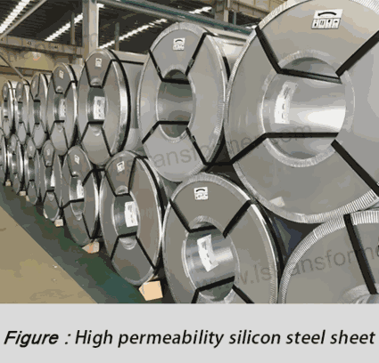
Core losses account for 30%-50% of total transformer losses, making advanced silicon steel sheets a fundamental measure for reducing temperature rise. At the microscopic level, cold-rolled grain-oriented (CRGO) silicon steel achieves over 85% Goss texture alignment (compared to 30%-40% in conventional silicon steel), ensuring the magnetization direction aligns with the easy axis and reducing hysteresis losses by 40%-60%. Research by JFE Steel Corporation shows that 0.23mm-thick 30JG120 silicon steel exhibits a unit loss of only 1.10W/kg at 1.7T working flux density, a 25% reduction compared to traditional 0.3mm silicon steel.
Key parameters for practical engineering applications include:
(1) Thickness selection:0.23mm silicon steel reduces eddy current losses by 15% compared to 0.27mm but increases costs by 20%.
(2) Coating technology:Phosphate-silicate composite insulation coatings achieve interlamination resistance exceeding 100Ω·cm².
(3) Magnetostriction control:Laser scribing reduces the magnetostriction coefficient to below 0.5ppm, minimizing vibration-induced heating.
| Parameter | Conventional Silicon Steel (0.3mm) | Advanced CRGO (0.23mm) | Amorphous Alloy |
| Unit Loss (W/kg) | 1.50 | 1.10 | 0.20 |
| Flux Density (T) | 1.65 | 1.80 | 1.40 |
| Fill Factor | 0.95 | 0.93 | 0.85 |
| Cost Index | 1.0 | 1.8 | 3.5 |
| Temp. Rise Reduction (K) | Baseline | 8-12 | 15-20 |
1.2 Fluid Dynamics and Electromagnetic Analysis of Joint Structure Innovation
Non-uniform flux distribution at core joints creates localized hot spots. Multiphysics optimization can significantly mitigate this issue. A 45° mitered joint design reduces the flux turning angle from 90° to 45°, lowering peak flux density at the joint from 1.8T to 1.5T and reducing localized losses by 35%. ABB’s practice shows that a five-step stepped joint with a 0.5mm gap reduces no-load current by 12%, corresponding to a 4-6K drop in core temperature rise.
Key technical points:
(1) Joint angle optimization:45° mitered joints reduce transverse leakage flux by 50% compared to butt joints.
(2) Stepped design:Three-step joints smooth flux transition, reducing joint temperature rise by 3-5K.
(3) Laser treatment:Local laser irradiation refines grain size to 20-30μm in joint areas.
2. Winding System Design: From Conductor Selection to Thermal Field Optimization
2.1 Electro-Thermal Coupling Principles for Conductor Materials
The AC resistance of winding conductors directly affects load losses, requiring consideration of skin and proximity effects. When the conductor thickness d exceeds 1.5 times the penetration depth δ (δ ≈ 9.3mm for copper at 50Hz), AC resistance increases sharply. Transposed conductors address this issue by periodically rotating strands (every 5-10mm), equalizing current distribution and limiting circulating losses to <5% of total losses.
2.1.1 Engineering considerations:
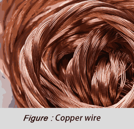
(1) Conductor shape:Flat copper wires with a 3:1 width-to-thickness ratio reduce AC resistance by 15% compared to round wires.
(2) Transposition pitch:For windings carrying >1000A, a pitch ≤8mm is recommended.
(3) Insulation system:Nomex® insulation paper (180°C rating) at 0.05mm thickness achieves a fill factor of 0.85.
2.1.2 The corrected AC resistance formula:
Rac = Rdc[1 + 0.00393(T-20)]·(1 + kₛ·F(d/δ) + kₚ·G(s/d))
場所:
k = skin effect coefficient (0.8-1.2)
k = proximity effect coefficient (0.5-1.0)
F, G = empirical functions
2.2 Active Thermal Field Control Strategies
CFD analysis shows traditional continuous windings exhibit axial temperature gradients of 15-20K, while axial split windings with directed oil ducts limit this to 8K. Siemens Energy’s case study on an 800kVA transformer demonstrated a 12K reduction in hotspot temperature using:
(1) Radial partitioning:Four parallel paths reduce current density from 3.2 to 2.6A/mm².
(2) Axial oil ducts:6mm vertical ducts increase oil velocity from 0.1m/s to 0.25m/s.
(3) End shielding:Copper electrostatic rings reduce end-field intensity from 3.5kV/cm to 2.0kV/cm.
3. Cooling System Innovations: From Passive to Smart Control
3.1 Multi-Scale Optimization of Oil Flow Systems
Heat dissipation in oil-immersed transformers depends on oil flow organization. Optimized directed cooling improves heat transfer coefficient h by 30%-50%:
Nu = 0.023·Re^0.8·Pr^0.4
(Nu = Nusselt number, Re = Reynolds number, Pr = Prandtl number)
Key practices:
(1) Oil duct sizing:6-8mm ducts optimize turbulence (Re≈4000).
(2) Flow velocity:0.2-0.3m/s balances pressure drop and heat transfer.
(3) Advanced oils:Synthetic esters offer 15% lower viscosity and 20% higher h than mineral oil.
3.2 Dynamic Response of Smart Cooling Systems
IoT-based systems adjust cooling in real-time:
(1) Fan control:Intermittent operation at <60% load reduces energy use by 40%.
(2) Variable-speed pumps:Frequency control cuts pump power by 50% at partial load.
(3) Heat pipes:Handle hotspot heat fluxes up to 50W/cm².
4. Evolving Standards and Future Trends
4.1 Latest efficiency standards impose stricter limits:
(1) IEC 60076-14:2019:Real-time hotspot monitoring required.
(2) IEEE C57.91-2011:Top-oil temperature rise limit reduced from 60°C to 55°C.
(3) China GB 20052-2020:Tier-1 transformers must cut no-load losses by 20%.
4.2 Emerging technologies:
(1) Digital thermal management:Real-time temperature field prediction via digital twins.
(2) Nanofluids:30%+ higher heat transfer coefficients.
(3) Superconductors:High-temperature superconducting transformers eliminate copper losses.
概要
Optimizing temperature rise requires a holistic “material-structure-control” approach. Combined measures can reduce temperature rise by 15-25K, boost efficiency by 0.8%-1.5%, and cut annual CO₂ emissions by 5-10 tons (per 1000kVA transformer). Manufacturers should adopt multiphysics design platforms to integrate temperature control across the product lifecycle.
連絡先
廬山,est。 1975年には中国の専門職の専門メーカーの電力変圧器及び原子炉のための50+る。 主製品 単相トランス、三相絶縁変圧器、電気トランス、物流トランス、ステップの下、信用リスク以外のリスクにつきトランス、低電圧トランス、高電圧トランス、制御トランス、トロイダルトランス、Rコアトランス直流インダクター、AC炉では、フィルタリング炉、負荷炉chokes、フィルタリングの原子炉は、中間体、高周波製品.
当社の電力変圧器及び原子炉に広く使用されて10アプリケーション:高速鉄道、建設機械、再生可能エネルギー、ロボット、医療機器、炭鉱爆発の防止、励起システム、真空焼結(炉)、中央エアコンがあります。
知電源トランス原子炉: www.lstransformer.com.
希得のカスタマイズソリューションのためのトランスや原子炉、お問い合わせください。
WhatsApp:+86 13787095096
メール:marketing@hnlsdz.com

