Wie lässt sich ein plötzlicher Kurzschlussausfall bei Transformatoren verhindern? – Analyse der Kurzschlussfestigkeit und Lösungen zur strukturellen Verstärkung
Wie kann ein plötzlicher Kurzschlussausfall des Transformators verhindert werden?
—Analyse der Kurzschlussfestigkeitsprüfung und struktureller Verstärkungslösungen
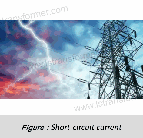
In Stromnetzen und der industriellen Verteilung ist der plötzliche Kurzschluss des Transformators, der zu Wicklungsverformungen und Isolationsdurchschlägen führt, zu einer globalen Herausforderung für die Zuverlässigkeit elektrischer Geräte geworden. LautIEEE C57.12.00 Statistiken zufolge können Kurzschlussströme Wicklungen elektromagnetischen Kräften von über 100 kN aussetzen, was dazu führt, dass 40 % der Transformatoren nach dem ersten Kurzschluss ausfallen. Dieser Artikel erläutert systematisch Verfahren zur Überprüfung der Kurzschlussfestigkeit und Technologien zur Strukturverstärkung basierend auf internationalen Standards wieIEC 60076-5 mit einem IEEE C57.12.90, unterstützt durch regionsübergreifende technische Validierungsdaten.
Inhalt
1. Zerstörungsmechanismus und Risikoquantifizierung von Kurzschlussströmen
● Elektromagnetische Krafteinwirkung des Kurzschlussstroms
(1)Kurzschlussstromberechnung und elektromagnetische
Krafterzeugung: Wenn auf der Sekundärseite des Transformators ein Kurzschluss auftritt, steigt der Primärstrom auf das 10- bis 25-fache seines Nennwerts, der durch den Prozentsatz (%) der Impedanzspannung des Transformators bestimmt wird.
Formel:

Variablendefinitionen:
 : Systemnennspannung
 : Impedanzspannung in Prozent (typischer Bereich: 4 %–12 %)
 : Transformator-Nennstrom
Ejemplo: Ein 1000 kVA Transformator mit Z%=6% und INenn = 1443A hat einen Kurzschlussstrom von:

(2)Direkte mechanische Schäden durch elektromagnetische
Kräfte Gemäß der Lorentzkraftformel betragen die elektromagnetischen Kräfte zwischen benachbarten Wicklungsleitern:

Variablendefinitionen:
 : Streuflussdichte (0.5–1.2 T, bestimmt durch Wicklungsabstand und Strom)
 :Kurzschlussstrom
 : effektive Leiterlänge
Ejemplo:Wenn B=0.8T und L=2m, beträgt die Kraft: F=0.8×24,050×2=38,480N(≈38.5kN)
Fehlermodi:
Axiale Kompression: Auf Hochspannungswicklungen wirkt ein Innendruck, der zu einer Quetschung der Isolierung zwischen den Windungen führt.
Radiale Ausdehnung: Niederspannungswicklungen dehnen sich nach außen aus, was zu Brüchen der Stützstreben und schließlich zum Zusammenbruch führt.
● Thermische Effekte und Isolationsverschlechterung
(1) Joule-Heizmechanismus:
Kurzschlussstrom erzeugt über den Wicklungswiderstand Wärme:

Variablendefinitionen:
·R: Wicklungswiderstand (Ω)
·t: Kurzschlussdauer (typischerweise ≤2 Sekunden)
·c: Spezifische Wärmekapazität (Kupfer: 385 J/kg·K)
·m: Leitermasse
Ejemplo: Für einen 50 kg schweren Kupferleiter mit AIsc =24kA und t=1s:

(2)Isolationsfehlerprozess:
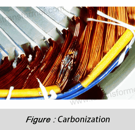
·Thermische Zersetzung: Epoxidharz verkohlt, wenn die Temperatur 105 °C (Isolationsgrenze der Klasse A) überschreitet.
·Reduzierung der Durchschlagsfestigkeit: Die Durchschlagspannung des Isolierpapiers sinkt pro 5 °C Temperaturanstieg um 8–10 % (IEC 60076-5).
·Kurzschlüsse zwischen den Windungen: Die Teilentladungs-Einsatzspannung sinkt von 15 kV auf unter 6 kV und verursacht bleibende Schäden.
2. Internationale Standards für die Überprüfung der Kurzschlussfestigkeit
● IEC 60076-5:Kernstandard für dynamische Stabilitätsprüfungen für Transformatoren ≤35 kV.
(1)Testprozedur:
·Zustand vor Kurzschluss:Nennstrom anlegen; Temperatur und Vibration überwachen.
·Kurzschlussimpuls:Legen Sie bei einer Abgriffsposition von 75 % für 0.25 Sekunden einen symmetrischen Strom an.
·Wiederholen Sie den Vorgang dreimal, um den Gesamtschaden zu ermitteln.
(2)Bestehenskriterien:
·Reaktanzänderung ≤2 %
·Wicklungsverformung ≤1.5 mm (gemessen über Laser-Wegsensoren).
● IEEE C57.12.90:Validierung der mechanischen Festigkeit. Schlüsselstandard für Transformatoren mit großer Kapazität in Nordamerika.
(1)Anforderungen:
Leistung (kVA) | Kurzschlusszyklen | Axialkraftgrenze (kN) |
≤ 2500 | 3 | 80 |
2501-10,000 | 2 | 150 |
> 10,000 | 1 | 300 |
(2)Testmethoden:
·Statische Drucksimulation mit Hydraulikzylindern (60 Sekunden halten).
·Schwingfrequenzdurchlauf (10–2000 Hz); Eigenfrequenzverschiebung ≤5 %.
3. Strukturelle Verstärkungslösungen für verbesserte Kurzschlussfestigkeit
● Optimierte Wicklungsunterstützungssysteme
(1)Verstärkungstechniken:
·Epoxidharzimprägnierte Streben:
Glasfaserverstärktes Epoxid (Biegefestigkeit ≥350 MPa, 4× stärker als Holz) reduziert die radiale Verformung von 3.2 mm auf 0.8 mm.
·Axialkompressionssysteme:
Tellerfederpakete (Vorspannung ≥50 kN) mildern axiale Kompression, wodurch die Zyklenzahl von 1 auf 3 erhöht wird (gemäß IEC 60076-5).
(2)Leistungsvergleich:
Parameter | Traditionell | Verstärkt |
Axiale Verformung (mm) | 3.2 | 0.8 |
Kurzschlusszyklen | 1 | 3 |
● Verbesserungen der Kern- und Klemmstruktur
(1)Verstärkungstechniken:
·Siliziumstahl mit geringer Hysterese: 23ZDKH90-Stahl reduziert die Übertragung der Kernvibrationsenergie um 40 % und vermeidet Resonanz (konform mit ISO 10816-3).
·Mehrlagig verschweißte Schellen: Q345B-Stahl (Streckgrenze 345 MPa, 47 % höher als Q235) absorbiert 300 kN Axialkräfte (erfüllt IEEE C57.12.90).
(2)Mechanische Eigenschaften:
Material | Streckgrenze (MPa) | Dämpfungsverhältnis (ξ) |
Q235 Stahl | 235 | 0.02 |
Q345B Stahl | 345 | 0.05 |
Zusammenfassend
Fazit Moderne Transformatoren verstärkt durchIEC 60076-5 mit einemIEEE C57.12.90 Standards können standhalten Kurzschlussströme ≥50 kA (IEC Level 4). Weltweite Fallstudien zeigen eine Reduzierung der jährlichen Ausfallraten um 70 % (ABB 2023 Whitepaper). Für maßgeschneiderte Lösungen kontaktieren Sie unser technisches Team für Simulations-, Test- und Validierungsservices.
Kontakt
LuShan, Europäische Sommerzeit.1975, ist ein chinesischer professioneller Hersteller, spezialisiert auf Leistungstransformatoren und Reaktoren für50 Jahre. Führende Produkte sind Einphasentransformator, Dreiphasentransformator Isolierung Transformatoren, elektrischer Transformator, Verteiltransformator, Abwärts- und Aufwärtstransformator, Niederspannungstransformator, Hochspannungstransformator, Steuertransformator, Ringkerntransformator, R-Kern-Transformator;Gleichstrominduktoren, Wechselstromreaktoren, Filterreaktoren, Netz- und Lastreaktoren, Drosseln, Filterreaktoren und Zwischen- und Hochfrequenzprodukte.
Unsere Kraft Transformatoren und Reaktoren werden in zehn Anwendungsbereichen häufig eingesetzt: Schnellverkehr, Baumaschinen, erneuerbare Energien, intelligente Fertigung, medizinische Geräte, Explosionsschutz in Kohlebergwerken, Erregersysteme, Vakuumsintern (Öfen), zentrale Klimaanlagen.
Erfahren Sie mehr über Leistungstransformatoren und Reaktoren:www.lstransformer.com.
Wenn Sie maßgeschneiderte Lösungen für Transformatoren oder Drosseln wünschen, kontaktieren Sie uns bitte.
WhatsApp:+86 17267488565
E-Mail:Vertrieb@hnlsdz.com

 EN
EN
 FR
FR DE
DE ES
ES


