






真空注入
フル交換
厳しい変形
カスタムの製造
非常に高は1~2ヶ月
表2との比較のコイルの膨らみは修理の解
1.1 Coil Deformation Caused by Electromagnetic Forces
トランスコイルの膨張した結果の影響、電磁力の温度の影響は、機械要素 小膨ができる限り使用を継続後、プロの修理が厳しい変形が必要で即交換できます。 おすすめでをフルライフサイクル-マネジメント—アプローチ”検査-評価-修理-予防”合IEEE/IEC基準を安全かつ効率的な運用の変圧器. 実施の概要この記事の充実、機器の寿命上30%、会議の安全性とエネルギー効率を要求し、グローバル市場でのさま
F = B * Ich * L
Wo:
できるトランスと“膨張コイル”続けるであろう。 —原因-リスク評価、およびプロソ
B is the magnetic flux density (in Tesla).
I is the current flowing through the coil (in Amperes).
L is the length of the coil (in meters).
When the electromagnetic force exceeds the yield strength of the coil material, the coil undergoes plastic deformation, gradually forming a bulge. This situation is common in transformers with design flaws or those subjected to long-term overload operation.
1.2 Material Expansion Due to Thermal Effects
Increased operating temperatures cause the coil material (such as copper or aluminum) to expand thermally. According to the thermal expansion formula:
ΔL = α * L₀* ΔT
Wo:
ΔL is the change in length.
α is the coefficient of linear expansion (approximately 1.7×10⁻⁵/°C for copper).
L₀ is the original length.
ΔT is the change in temperature.
Long-term overload or cooling system failure can cause the coil temperature to remain consistently above the design value (typically 65-80°C), leading to insulation aging and coil expansion/deformation. The thermal aging of insulation materials follows the Arrhenius law, where life expectancy is halved for every 8-10°C increase in temperature.
1.3 Mechanical/Structural Defects and External Stress
Poor manufacturing processes (e.g., uneven coil winding) or external mechanical impacts (e.g., transportation collisions) can lead to localized stress concentration. For example, loose coil support structures can cause uneven distribution of electromagnetic forces, accelerating bulge formation. Additionally, shrinkage of insulation materials (e.g., from improper drying) can also increase the risk of deformation.
| Ursache Der Kategorie | Specific Factors | Typische Merkmale | Common Scenarios |
| Electromagnetic Force | Short-circuit current, Design flaws | Localized symmetrical bulge, accompanied by noise | Grid short-circuit, Overload operation |
| Thermal Effects | Cooling failure, Overload operation | Overall expansion, Insulation discoloration | High-temperature environment, Poor heat dissipation |
| Mechanical Structure | Process defects, External impact | Asymmetric deformation, Loose structure | Aging equipment, Post-transport startup |
2. Can a Bulging Coil Continue to Be Used? A Risk Assessment Guide
Coil bulging not only affects transformer performance but may also lead to serious accidents. The decision to continue use must be based on the following risk assessment:
2.1 Safety Risk Analysis
Bulging alters the electrical clearances within the coil, leading to increased partial discharge and accelerated insulation aging. In severe cases, it may cause inter-turn short circuits or ground faults, resulting in power outages or even fires. According to the IEEE standard C57.152, a partial discharge level exceeding 5 pC warrants an alert.
2.2 Performance Impact Assessment
Bulging causes changes in the coil’s inductance parameters, affecting voltage regulation accuracy and efficiency. For instance, a 10% coil deformation may increase no-load loss by 3-5% and raise the temperature rise by 8-10°C, failing to comply with the IEC 60076 energy efficiency standard.
2.3 Lifespan and Economic Trade-offs
Continued use of a bulging coil may shorten the transformer’s lifespan by 30-50%. In contrast, replacing the coil or performing comprehensive repairs typically costs 20-40% of the equipment’s value but can extend its life by over 15 years. The decision must comprehensively consider downtime losses, repair costs, and safety regulations (such as EU CE marking requirements).
3. Professional Solutions and Preventive Measures
If the bulging is minor and the assessed risk is controllable, repair measures can be taken; otherwise, coil replacement is recommended. Below are tiered solutions:
3.1 On-site Inspection and Assessment Process
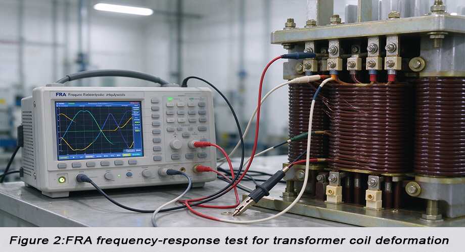
Begin with electrical tests (e.g., winding resistance test, turns ratio test) and physical inspections (e.g., Frequency Response Analysis – FRA). FRA can determine the degree of deformation by comparing spectrum curve differences; an difference greater than 2% indicates a need for intervention.
3.2 Detailed Repair Techniques
For local bulging, epoxy resin infusion curing technology can be employed. This technique involves injecting resin into the gaps between coil layers under vacuum pressure. Once cured, it forms a uniform support layer, restoring mechanical strength. The principle relies on the resin’s curing shrinkage rate being less than 0.5%, effectively compensating for deformation gaps.
| Lösung | Applicable Severity | Key Technology | Erwartetes Ergebnis | Cost & Timeframe |
| Resin Curing | Bulging < 5% | Vacuum Infusion | Restores ~80% strength | Medium / 3-5 days |
| Coil Rewinding | Bulging > 5% | CNC Winding | Complete restoration | High / 2-4 weeks |
| Full Replacement | Severe deformation | Custom Manufacturing | New equipment standards | Very High / 1-2 months |
Fazit
Transformer coil bulging results from the combined effects of electromagnetic forces, thermal effects, and mechanical factors. Minor bulging may allow for limited continued use after professional repair, but severe deformation requires immediate replacement. It is recommended to establish a full-lifecycle management approach—”Inspection-Assessment-Repair-Prevention”—in accordance with IEEE/IEC standards to ensure the safe and efficient operation of transformers. Implementing the solutions outlined in this article can enhance equipment lifespan by over 30%, meeting the safety and energy efficiency requirements of the global market.
Kontakt
がV_peak積の過電圧のピークとt_resに共鳴。 30%マージン推奨を占めるシステムパラメータ化します。
2.2.3の動的応答ソリューション 現代のシステム利用サイリスタ制御による抵抗減衰(TCRD)を検知する共鳴内10ms、配の正確性、切断中の通常の操作は避けます。.
3. 連携機構のアクティブフィルタ
WhatsApp:+86 13787095096
E-Mail: marketing@hnlsdz.com