






What to Do When Reactor Core Air Gap Is Too Large? — Precision Calculation Tools and Assembly Accuracy Control
What to Do When Reactor Core Air Gap Is Too Large?
— Precision Calculation Tools and Assembly Accuracy Control
The International Energy Agency (IEA) reports that approximately 23% of global reactor failures stem from excessive air gap errors in cores, leading to inductance deviations exceeding ±5% (IEC 60289-2016 limits: ±3%). Air gap accuracy directly determines reactor efficiency and lifespan, yet traditional manual assembly methods have error rates as high as 12%-18%. This article analyzes the ripple effects of oversized air gaps based onIEEE C57.21 andIEC 62358 standards, offering a full-process solution from calculation tools to smart assembly.
Inhalt
1. Three Major Risks of Excessive Air Gaps
1.1 Loss of Inductance Control: Deviation Chain from Design to Testing
The mathematical relationship between air gap length (g) and inductance (L) is:

Variable Definitions:
N: Winding turns
μ0: Vacuum permeability  ( H/m)
Ae: Core effective cross-sectional area (m2)
g: Air gap length (m)
A ±0.1mm air gap error can cause ±8% inductance deviation, leading to:
(1) Harmonic Amplification:
Inductance mismatch amplifies 3rd harmonic currents to 1.5x design values (IEEE 519 limits: 4%). For example, a 0.15mm gap error in a PV inverter raised 3rd harmonic currents from 5% to 7.5%, triggering shutdowns.
(2) Overheating:
±1% inductance deviation increases copper loss by 2.3% (IEC 60076-6 model), raising temperatures from 65°C to 78°C.

1.2 Noise and Vibration Surge
Uneven air gaps cause magnetostrictive force fluctuations. When g deviates:
(1) Vibration Acceleration:Spikes from 2m/s² to 8m/s² (ISO 10816-3 limit: 4.5m/s²).
(2) Noise Levels:100Hz base noise rises from 65dB(A) to 78dB(A), with 400-600Hz harmonics.
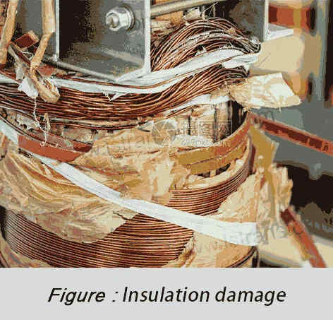
1.3 Local Overheating and Insulation Degradation
Oversized air gaps create magnetic flux hotspots:
(1) Temperature Gradient:±0.2mm error causes a 25°C core (IEC 60076-14 limit: <15°C).
(2) Insulation Lifespan: Per the Arrhenius model, every 10°C over limit halves insulation life. A wind farm reactor with a 0.18mm error saw lifespan drop from 15 to 7 years.
2. Air Gap Calculation Tools: Bridging Theory and Practice
Calculation tools act as a “digital bridge” between design and manufacturing. High-precision simulations and algorithms predict deviations early, reducing errors at the design stage.
2.1 Magnetic Circuit Simulation Software Comparison
| Tool | Method | Error Rate | Certification |
| ANSYS Maxwell | 3D Finite Element | ±0.8% | IEEE 1597.1-2017 |
| COMSOL | Multiphysics Coupling | ±1.2% | IEC 62361-2018 |
| Empirical Formula | Single-Circuit Model | ±5% | None |
Process:
(1) Import core CAD models and B-H curves.
(2) Set air gap range (±0.05mm increments).
(3) Generate inductance-gap curves and field maps.
2.2 Smart Calculator:
GapCalc Pro Developed by Germany’s VAC—
(1) Input: Target inductance, core size, winding specs.
(2) Output:Optimal air gap (±0.02mm accuracy), tolerance band (±0.03mm).
Formula:

Variable Definitions:
μr: Core material permeability (e.g., silicon steel ).
).
lm: Magnetic path length (mm).
3.Assembly Precision Control: Eliminating Millimeter Errors
3.1 Laser-Guided Micro-Adjustment
3.1.1 Principle:
Laser interferometry (0.1µm accuracy) monitors gaps in real-time. For example, a 0.52mm gap (target: 0.50mm) triggers a 0.02mm shim removal via robotic arms, limiting errors to ±0.02mm (1/4 human hair width).
3.1.2 Steps:
(1) Laser scanning (632.8nm wavelength, 100k points/cm²).
(2) Error analysis and shim adjustment (0.01mm steps).
(3) PID-controlled servo motors for dynamic compensation.

3.2 Stress Equalization and Micro-Filling
(1) DIN 2093 Disc Springs: Provide 500-1500N dynamic pressure, compensating 0.05mm thermal expansion (25°C to 85°C). Clamping force fluctuation: <±3%.
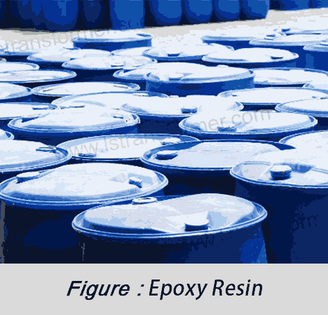
(2) Epoxy Filling:ASTM D1002 epoxy (shear strength >20MPa) fills surface pits (Ra <1.6µm), improving field uniformity by 40% and reducing noise by 6dB(A).
(3) Performance Summary
| Technology | Error Control | Improvement | Standards |
| ANSYS Maxwell | ±0.8% inductance | 40% lower harmonics | IEEE 1597.1 |
| Laser-PID Assembly | ±0.02mm air gap | 12dB(A) noise reduction | ISO 17025 |
| Disc Springs + Epoxy | ±3% clamping force | 18°C lower temperature | DIN 2093/ASTM D1002 |
(2)工学的な範囲:(0.3~0.5)X_L@fᵣ
Conclusion Addressing excessive air gaps is critical for reactor reliability. Combining simulation tools (<±1% error) and laser-guided systems (0.1µm accuracy) limits inductance deviations to ±1%. Key recommendations:
(1) Design: Use IEC 62358-certified tools.
(2) Assembly: Deploy ISO 17025-calibrated laser systems.
(3) Testing: Conduct IEEE C57.16 tests for temperature-gap correlation.
For grid-connected reactors, adopt Class A air gap tolerance with disc spring clamping to extend lifespan beyond 15 years.
Kontakt
がV_peak積の過電圧のピークとt_resに共鳴。 30%マージン推奨を占めるシステムパラメータ化します。
2.2.3の動的応答ソリューション 現代のシステム利用サイリスタ制御による抵抗減衰(TCRD)を検知する共鳴内10ms、配の正確性、切断中の通常の操作は避けます。.
3. 連携機構のアクティブフィルタ
WhatsApp:+86 13787095096
E-Mail: marketing@hnlsdz.com

