






How to prevent Transformer Sudden Short-Circuit Failure? —Analyzing Short-Circuit Resistance Verification and Structural Reinforcement Solutions
How to prevent Transformer Sudden Short-Circuit Failure?
—Analyzing Short-Circuit Resistance Verification and Structural Reinforcement Solutions
In power grid systems and industrial distribution, “transformer sudden short-circuit leading to winding deformation and insulation breakdown” has become a global challenge for electrical equipment reliability. According toIEEE C57.12.00 statistics, short-circuit current impacts can subject windings to electromagnetic forces exceeding 100 kN, causing 40% of transformers to fail after their first short-circuit event. This article systematically explains short-circuit resistance verification processes and structural reinforcement technologies based on international standards likeIEC 60076-5 and IEEE C57.12.90, supported by cross-regional engineering validation data.
Contenido
1. Destruction Mechanism and Risk Quantification of Short-Circuit Current
1.1 Electromagnetic Force Impact of Short-Circuit Current
1.1.1 Short-Circuit Current Calculation and Electromagnetic
Force Generation When a short-circuit occurs on the transformer’s secondary side, the primary current surges to 10–25 times its rated value, determined by the transformer’s impedance voltage percentage (%).
(1) Formula:

(2) Variable Definitions:
 : System rated voltage
 : Impedance voltage percentage (typical range: 4%–12%)
 : Transformer rated current
(3) Example: A 1000 kVA transformer with Z%=6% and Irated = 1443A has a short-circuit current of:


1.1.2 Direct Mechanical Damage from Electromagnetic
Forces Per the Lorentz force formula, electromagnetic forces between adjacent winding conductors are:

(1) Variable Definitions:
 : Leakage flux density (0.5–1.2 T, determined by winding spacing and current)
 :Short-circuit current
 : Conductor effective length
(2) Example:If B=0.8T and L=2m, the force is: F=0.8×24,050×2=38,480N(≈38.5kN)
(3) Failure Modes:
Axial Compression: High-voltage windings experience inward pressure, leading to inter-turn insulation crushing.
Radial Expansion: Low-voltage windings expand outward, causing support strut fractures and eventual collapse.
1.2 Thermal Effects and Insulation Degradation
1.2.1 Joule Heating Mechanism:
Short-circuit current generates heat via winding resistance:

(1) Variable Definitions:
R: Winding resistance (Ω)
t: Short-circuit duration (typically ≤2 seconds)
c: Specific heat capacity (copper: 385 J/kg·K)
m: Conductor mass
(2) Example: For a 50 kg copper conductor with AIsc =24kA and t=1s:

1.2.2 Insulation Failure Process:
(1) Thermal Decomposition: Epoxy resin carbonizes when temperatures exceed 105°C (Class A insulation limit).
(2) Dielectric Strength Reduction: Insulation paper breakdown voltage drops 5%–8% per 10°C rise (IEC 60076-5).
(3) Inter-Turn Short Circuits: Partial discharge inception voltage falls from 15 kV to below 6 kV, causing permanent damage.
2.International Standards for Short-Circuit Resistance Verification
2.1 IEC 60076-5:Dynamic Stability Testing Core standard for transformers ≤35 kV.
2.1.1 Test Procedure:
(1) Pre-short-circuit state:Apply rated current; monitor temperature and vibration.
(2) Short-circuit impulse:Apply symmetrical current at 75% tap position for 0.25 seconds.
(3) Repeat three times to assess cumulative damage.
2.1.2 Pass Criteria:
(1) Reactance change ≤2%
(2) Winding deformation ≤1.5 mm (measured via laser displacement sensors).
2.2 IEEE C57.12.90:Mechanical Strength Validation Key standard for large-capacity transformers in North America.
2.2.1 Requirements:
| Capacity (kVA) | Short-Circuit Cycles | Axial Force Limit (kN) |
| ≤2500 | 3 | 80 |
| 2501–10,000 | 2 | 150 |
| >10,000 | 1 | 300 |
2.2.2 Test Methods:
(1) Static pressure simulation using hydraulic cylinders (60-second hold).
(2) Vibration frequency sweep (10–2000 Hz); natural frequency shift ≤5%.
3. Structural Reinforcement Solutions for Enhanced Short-Circuit Resistance
3.1 Optimized Winding Support Systems
3.1.1 Reinforcement Techniques:
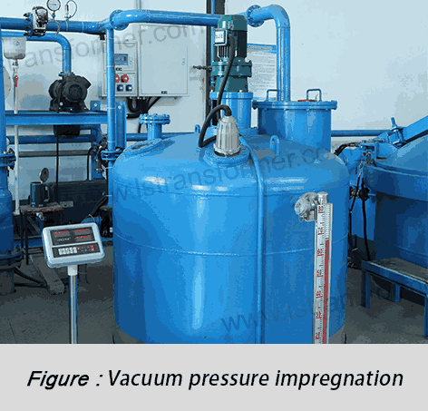
(1) Epoxy-Resin Impregnated Struts:
Glass-fiber-reinforced epoxy (bending strength ≥350 MPa, 4× stronger than wood) reduces radial deformation from 3.2 mm to 0.8 mm.
(2) Axial Compression Systems:
Disk spring assemblies (preload ≥50 kN) mitigate axial compression, increasing withstand cycles from 1 to 3 (per IEC 60076-5).
3.1.2 Performance Comparison:
| Parámetro | Traditional | Reinforced |
| Axial Deformation (mm) | 3.2 | 0.8 |
| Short-Circuit Cycles | 1 | 3 |
3.2 Core and Clamping Structure Enhancements
3.2.1 Reinforcement Techniques:
(1) Low-Hysteresis Silicon Steel: 23ZDKH90 steel reduces core vibration energy transfer by 40%, avoiding resonance (ISO 10816-3 compliant).
(2) Multi-Layer Welded Clamps: Q345B steel (yield strength 345 MPa, 47% higher than Q235) absorbs 300 kN axial forces (meets IEEE C57.12.90).
3.2.2 Mechanical Properties:
| Material | Yield Strength (MPa) | Damping Ratio (ξ) |
| Q235 Steel | 235 | 0.02 |
| Q345B Steel | 345 | 0.05 |
En Resumen
Conclusion Modern transformers reinforced viaIEC 60076-5 andIEEE C57.12.90 standards can withstand ≥50 kA short-circuit currents (IEC Level 4). Global cases show a 70% reduction in annual failure rates (ABB 2023 Whitepaper). For customized solutions, contact our technical team for simulation, testing, and validation services.
Contacto
LuShan, est. En 1975, es un Chino fabricante profesional que se especializa en los transformadores de potencia y reactores de más de 50 años. Los productos principales son transformador monofásico, trifásico de transformadores de aislamiento, transformador eléctrico, transformador de distribución, el paso hacia abajo y paso transformador de baja tensión del transformador, transformador de alto voltaje, transformador de control, transformador toroidal, R-transformador con núcleo; DC inductores, CA reactores, filtrado de reactor de línea y de carga del reactor, estrangulaciones, el filtrado de los reactores y de los intermedios, de alta frecuencia de los productos.
Nuestros transformadores de potencia y reactores son ampliamente utilizados en las 10 áreas de aplicación: rapid transit, maquinaria de construcción, energía renovable, de fabricación inteligentes, equipos médicos, la mina de carbón de la explosión de la prevención, el sistema de excitación, de vacío, de sinterización(horno), aire acondicionado central.
Saber más acerca de transformadores de potencia y reactores: www.lstransformer.com.
Si desea obtener soluciones personalizadas para transformadores o reactores, póngase en contacto con nosotros.
WhatsApp:+86 13787095096
Correo electrónico: marketing@hnlsdz.com

