How to Improve Harmonic Filtering Efficiency of Reactors? —Exploring Impedance Frequency Characteristics and Topology Optimization

ホーム > 投稿者: 369703005 > ページ 32
FAQ

How to Improve Harmonic Filtering Efficiency of Reactors? —Exploring Impedance Frequency Characteristics and Topology Optimization

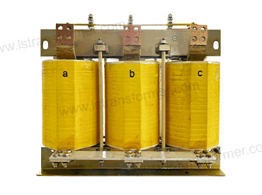
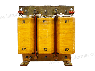
How to Improve Harmonic Filtering Efficiency of Reactors? —Exploring Impedance Frequency Characteristics and Topology Optimization According to the International Energy Agency (IEA), inadequate harmonic filtering efficiency in reactors results in annual global energy losses of $32 billion, particularly in 3rd and 5th harmonic frequency bands (150–300 Hz). Traditional reactors struggle with impedance mismatch and thermal management. Based on IEC 61000-4-7 andIEEE 1531 standards, this article analyzes three engineering pathways to enhance filtering efficiency: material innovation, magnetic circuit optimization, and topology upgrades. Content 1. Three Bottlenecks in Harmonic Filtering Efficiency 1.1 Impedance-Frequency Characteristic Mismatch Traditional reactors exhibit linear impedance growth with frequency, failing to meet harmonic filtering demands: (1) Mechanism: At 50 Hz (fundamental frequency), […]
FAQ

Why Do Transformer Standby Costs Surpass Millions? ​—Transformer Energy Efficiency Optimization & Smart Power-Saving Technologies Explained

Why Do Transformer Standby Costs Surpass Millions? —Transformer Energy Efficiency Optimization & Smart Power-Saving Technologies Explained As global energy costs rise and carbon neutrality goals advance, transformer no-load loss has become a significant “hidden energy drain” in industrial sectors. According to the International Energy Agency (IEA), approximately 35% of industrial transformers worldwide exceed no-load loss limits, wasting over 200 billion kWh annually—equivalent to 800 million tons of CO₂ emissions. Following standards like IEC 60076-27 (transformer efficiency) and IEEE C57.12.90 (no-load loss testing), no-load losses account for 20%-30% of a transformer’s lifecycle costs, with high-consumption industries losing over $1 million annually. This article analyzes the root causes of no-load losses through

FAQ

Why Does Solar Power Plant Output Drop Suddenly? —Core Causes and Smart Solutions for Reactor Failures

Why Does Solar Power Plant Output Drop Suddenly? —Core Causes and Smart Solutions for Reactor Failures As global photovoltaic (PV) capacity exceeds 1 terawatt (TW), solar plant operators face growing operational challenges. According to the International Energy Agency (IEA), 23% of solar power generation losses are directly linked to reactor failures, causing annual economic losses exceeding $5 billion. This article analyzes the root causes of reactor malfunctions and provides actionable solutions to restore 99% power generation efficiency, ensuring long-term profitability for solar plants. Content 1. Three Core Causes of Reactor Failures in Solar Plants 1.1 Harmonic Resonance: The Invisible Threat to Inverters and Grids (1) Issue: PV inverters generate 5th and

FAQ

Insufficient Reactor Reactive Power Compensation? —Dynamic Regulation Algorithms & Capacity Expansion Guide

Insufficient Reactor Reactive Power Compensation? —Dynamic Regulation Algorithms & Capacity Expansion Guide   1. Three Root Causes of Reactive Power Deficiency 1.1 Load Fluctuations & Delayed Response Modern grids face wind/solar power fluctuations up to ±30%/minute. Traditional reactors (TCR/MCR) respond in seconds to minutes, causing power factor drops below 0.8 when load changes outpace device response. Consequences include: (1) Voltage fluctuations:±10% deviations trigger equipment shutdowns (exceeding IEC 61000-4-30’s ±5% limit). (2) Additional losses: Line losses rise by 1.2% per 0.01 power factor drop (IEEE 141 formula). Case Study:A California wind farm incurred $120k/quarter in fines due to TCR’s 500ms delay causing voltage violations. 1.2 Harmonic Pollution Synergy Power electronics generate 5th/7th harmonics

FAQ

How to prevent Transformer Sudden Short-Circuit Failure? —Analyzing Short-Circuit Resistance Verification and Structural Reinforcement Solutions

How to prevent Transformer Sudden Short-Circuit Failure? —Analyzing Short-Circuit Resistance Verification and Structural Reinforcement Solutions In power grid systems and industrial distribution, “transformer sudden short-circuit leading to winding deformation and insulation breakdown” has become a global challenge for electrical equipment reliability. According toIEEE C57.12.00 statistics, short-circuit current impacts can subject windings to electromagnetic forces exceeding 100 kN, causing 40% of transformers to fail after their first short-circuit event. This article systematically explains short-circuit resistance verification processes and structural reinforcement technologies based on international standards likeIEC 60076-5 and IEEE C57.12.90, supported by cross-regional engineering validation data. Content 1. Destruction Mechanism and Risk Quantification of Short-Circuit Current 1.1 Electromagnetic Force Impact of Short-Circuit Current 1.1.1

FAQ

Why Do Reactor Core Losses Exceed Standards? —Complete Guide to Low-Loss Nanocrystalline Alloy Materials

Why Do Reactor Core Losses Exceed Standards? —Complete Guide to Low-Loss Nanocrystalline Alloy Materials According to the International Energy Agency (IEA), global power systems lose 21 billion kWh annually due to reactor core overheating—equivalent to the yearly electricity consumption of 24 million households. In the era of high-frequency, high-power electronics, traditional magnetic core materials have hit performance ceilings. This article reveals how nanocrystalline alloys, through atomic-level structural innovation, are revolutionizing low-loss reactor technology. Content 1. Three Sources of Core Loss & Material Performance Comparison 1.1 Core Loss Mechanisms Explained (1) Hysteresis Loss:  Like Repeated Friction Generating Heat Magnetic domain flipping in alternating fields consumes energy as internal “resistance.” Traditional silicon

FAQ

How to Choose Reactor Core Materials? — Comprehensive Guide to Silicon Steel, Ferrite, and Amorphous Alloys

How to Choose Reactor Core Materials? — Comprehensive Guide to Silicon Steel, Ferrite, and Amorphous Alloys In power systems, new energy inverters, and industrial frequency conversion equipment, “reactor core material selection” is a critical decision affecting efficiency, size, and cost. According toIEEE 389 standards, core materials directly determine 40%-60% of reactor losses. This article, based onIEC 60404 andASTM A927 international standards, systematically analyzes the magnetic properties of silicon steel, ferrite, and amorphous alloys, providing a global engineering selection guide. Content 1. Key Performance Parameters and Selection Logic 1.1 Core Performance Indicators The core parameters of magnetic materials determine reactor size, efficiency, and temperature rise: 1.1.1 Saturation Flux Density (Bsat): (1) Definition:Maximum magnetic flux

FAQ

What to Do When Reactor Core Air Gap Is Too Large? — Precision Calculation Tools and Assembly Accuracy Control

What to Do When Reactor Core Air Gap Is Too Large? — Precision Calculation Tools and Assembly Accuracy Control The International Energy Agency (IEA) reports that approximately 23% of global reactor failures stem from excessive air gap errors in cores, leading to inductance deviations exceeding ±5% (IEC 60289-2016 limits: ±3%). Air gap accuracy directly determines reactor efficiency and lifespan, yet traditional manual assembly methods have error rates as high as 12%-18%. This article analyzes the ripple effects of oversized air gaps based onIEEE C57.21 andIEC 62358 standards, offering a full-process solution from calculation tools to smart assembly. Content 1. Three Major Risks of Excessive Air Gaps 1.1 Loss of Inductance Control: Deviation Chain

FAQ

Why Does Transformer Noise Persist? —From Noise Source Identification to Targeted Solutions

Why Does Transformer Noise Persist? —From Noise Source Identification to Targeted Solutions According to the latest CIGRE survey, 29% of global operational transformers exhibit audible abnormal noise, with 18% of cases leading to equipment damage. Abnormal noise is not only an early sign of performance degradation but also a potential risk to grid safety. This guide integrates IEC 60076 and IEEE C57.12 standards to provide a systematic solution covering electromagnetic, mechanical, and environmental factors, offering actionable noise control strategies for global power enterprises. Content 1. Electromagnetic System Abnormalities: Hidden Causes of Noise 1.1 Root Causes (1) Magnetostriction Instability Silicon steel sheets generate periodic deformation (magnetostriction coefficient: 1-3 ppm) under alternating magnetic fields, with a

FAQ

Evolution of Transformer Winding Materials —Balancing Cost and Performance: From Electrolytic Copper to Copper-Clad Aluminum

Evolution of Transformer Winding Materials —Balancing Cost and Performance: From Electrolytic Copper to Copper-Clad Aluminum According to data from the International Copper Association (ICA), winding materials account for 35%-50% of a transformer’s total cost. Over the past 30 years, copper prices have surged by 380%, driving global manufacturers to explore low-cost alternatives. From pure electrolytic copper to copper-clad aluminum (CCA), copper-clad steel (CCS), and nano-coated composite conductors, this material revolution has profoundly impacted the performance and economic efficiency of power equipment. This article analyzes the evolution and future trends of winding materials based on standards such as IEC 60076-7 and IEEE C57.18.10. Content 1.The Era of Electrolytic Copper (1950–2000): The

WhatsAppにQR WeChat QR sales@hnlsdz.com
スクロールトップ