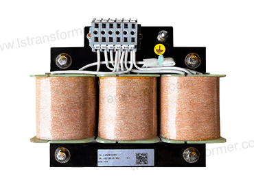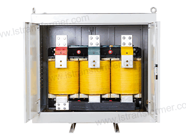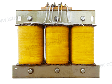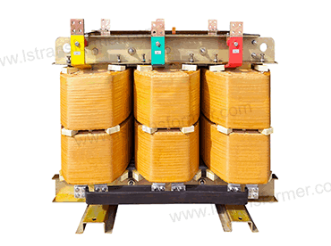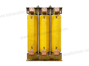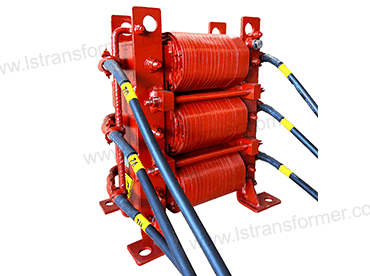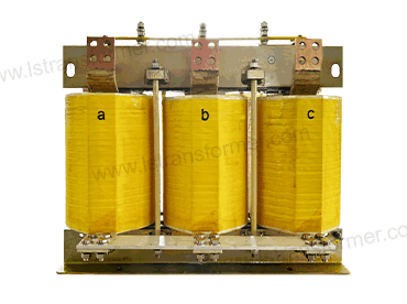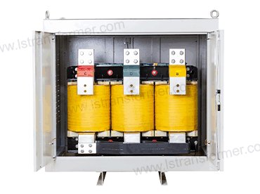
Evolution of Transformer Winding Materials —Balancing Cost and Performance: From Electrolytic Copper to Copper-Clad Aluminum

ホーム > FAQ > ページ 34
FAQ

Evolution of Transformer Winding Materials —Balancing Cost and Performance: From Electrolytic Copper to Copper-Clad Aluminum

Evolution of Transformer Winding Materials —Balancing Cost and Performance: From Electrolytic Copper to Copper-Clad Aluminum According to data from the International Copper Association (ICA), winding materials account for 35%-50% of a transformer’s total cost. Over the past 30 years, copper prices have surged by 380%, driving global manufacturers to explore low-cost alternatives. From pure electrolytic copper to copper-clad aluminum (CCA), copper-clad steel (CCS), and nano-coated composite conductors, this material revolution has profoundly impacted the performance and economic efficiency of power equipment. This article analyzes the evolution and future trends of winding materials based on standards such as IEC 60076-7 and IEEE C57.18.10. Content 1.The Era of Electrolytic Copper (1950–2000): The
FAQ

The Evolution of Transformer Core Materials: From Silicon Steel to Amorphous Alloys

​The Evolution of Transformer Core Materials: From Silicon Steel to Amorphous Alloys Driven by the global energy transition and carbon neutrality goals, the innovation of transformer core materials has become central to improving energy efficiency. This article explores the evolution of silicon steel, cold-rolled grain-oriented silicon steel, and amorphous alloys, covering their historical background, performance advantages and disadvantages, and application scenarios. Content 1. Silicon Steel (1903–Present) 1.1 Historical Background: In the early 20th century, the expansion of power systems created a surge in demand for efficient transformers. In 1903, British metallurgist Robert Hadfield invented silicon steel with 3%-5% silicon content. By doping silicon atoms, the electromagnetic properties of pure iron

FAQ

What Are Current Limiting Reactors? —The Secret Weapon for Power System Short Circuit Protection

What Are Current Limiting Reactors? —The Secret Weapon for Power System Short Circuit Protection According to the International Council on Large Electric Systems (CIGRE), short circuits are among the deadliest threats to power systems. Current limiting reactors suppress 60%-80% of fault currents, preventing over $8 billion in global equipment losses annually. This article, based on IEC 60076-6 and IEEE C57.16 standards, decodes the core principles and engineering practices of these reactors, revealing their role as the “invisible guardians” of grid safety. Content 1. The Destructive Power of Short Circuits & the Role of Current Limiting Reactors 1.1 The “Avalanche Effect” of Short Circuit Currents During a short circuit, current surges

FAQ

How to Reduce Leakage Flux in Transformers?

How to Reduce Leakage Flux in Transformers? — Applications of Silicon Steel Lamination, Copper Shielding Rings, and Magnetic Gap Fillers In power transmission and electronic devices, transformers play a critical role. However, leakage flux generated during transformer operation not only reduces efficiency but also causes electromagnetic interference (EMI), localized overheating, and noise. According to statistics from the International Energy Agency (IEA), losses in global distribution transformers account for approximately 2-3% of total power generation, with leakage flux contributing significantly. This article explores three internationally proven leakage flux suppression techniques: silicon steel lamination, copper shielding rings, and magnetic gap filler applications, helping you optimize transformer design for improved efficiency and reliability.

FAQ

どのように制御型変圧器の温度上昇に高温環境?

How to Control Transformer Temperature Rise in High-Temperature Environments? —Synergistic Design of Heat-Resistant Insulation Materials and Forced Air Cooling Against the backdrop of global warming and increasing industrial demand, the stable operation of transformers in high-temperature environments has become a major challenge for the power industry. This article delves into a comprehensive solution for controlling transformer temperature rise through the synergistic design of heat-resistant insulation materials and forced air cooling systems. It aims to help users understand the essence of this complex technical issue and the strategies to address it. Content 1. Impact of High-Temperature Environments on Transformers and the Importance of Temperature Rise Control Transformers, as core equipment in

FAQ

Can Lamination Process Optimization Reduce Leakage Flux?

Can Lamination Process Optimization Reduce Leakage Flux? —In-Depth Analysis of Winding Transposition and Core Step-Lap Joint Technology In the global wave of pursuing carbon neutrality, the energy consumption of power equipment has become a growing focus. According to data from the International Energy Agency (IEA), transmission and distribution losses account for approximately 8%-15% of global electricity generation. As core equipment in power grids, improving transformer efficiency is of great significance for energy conservation and emission reduction. The European Union (EU) Eco-Design Directive and the U.S. Department of Energy (DOE) energy efficiency standards continue to evolve, driving innovation in transformer loss-reduction technologies. Among these, leakage flux control—due to its decisive impact

FAQ

How Ambient Temperature Affects Temperature Rise? —Temperature Rise Correction Factors for High Altitude and Humid Regions

How Ambient Temperature Affects Temperature Rise? —Temperature Rise Correction Factors for High Altitude and Humid Regions Transformers and reactors, as core equipment in power systems, directly impact the stability of the entire grid. With the global deployment of power equipment, environmental factors affecting temperature rise have become a key focus of International Electrotechnical Commission (IEC) and IEEE standards. This article explores the mechanisms of ambient temperature, altitude, and humidity on transformer temperature rise and details internationally recognized correction factor calculations. This helps power engineers and procurement decision-makers accurately evaluate equipment performance under varying environmental conditions. Content 1. Fundamental Relationship Between Ambient Temperature and Transformer Temperature Rise Transformer temperature rise (ΔT)

FAQ

Reactor Vibration Causing Structural Cracks? —Dual Reinforcement with Seismic Brackets and Epoxy Resin Encapsulation

Reactor Vibration Causing Structural Cracks? —Dual Reinforcement with Seismic Brackets and Epoxy Resin Encapsulation In power systems, industrial frequency converters, and renewable energy plants, “structural cracks caused by reactor vibration” have become a critical challenge for engineers worldwide. According to IEEE 693-2018 research, vibration acceleration during reactor operation can exceed 2.5g, leading to a 60%-80% reduction in weld fatigue life over time. This article analyzes the synergistic reinforcement principles of seismic brackets and epoxy resin encapsulation, aligned with international standards like ASCE/SEI 7-22 and IEC 60076-6, and provides globally validated engineering data. Content 1. Damage Mechanism and Risk Quantification of Reactor Vibration 1.1 Vibration Sources and Energy Transmission Paths (1) Electromagnetic

FAQ

How to Improve Harmonic Filtering Efficiency of Reactors? —Exploring Impedance Frequency Characteristics and Topology Optimization

How to Improve Harmonic Filtering Efficiency of Reactors? —Exploring Impedance Frequency Characteristics and Topology Optimization According to the International Energy Agency (IEA), inadequate harmonic filtering efficiency in reactors results in annual global energy losses of $32 billion, particularly in 3rd and 5th harmonic frequency bands (150–300 Hz). Traditional reactors struggle with impedance mismatch and thermal management. Based on IEC 61000-4-7 andIEEE 1531 standards, this article analyzes three engineering pathways to enhance filtering efficiency: material innovation, magnetic circuit optimization, and topology upgrades. Content 1. Three Bottlenecks in Harmonic Filtering Efficiency 1.1 Impedance-Frequency Characteristic Mismatch Traditional reactors exhibit linear impedance growth with frequency, failing to meet harmonic filtering demands: (1) Mechanism: At 50 Hz (fundamental frequency),

FAQ

Why Do Transformer Standby Costs Surpass Millions? ​—Transformer Energy Efficiency Optimization & Smart Power-Saving Technologies Explained

Why Do Transformer Standby Costs Surpass Millions? —Transformer Energy Efficiency Optimization & Smart Power-Saving Technologies Explained As global energy costs rise and carbon neutrality goals advance, transformer no-load loss has become a significant “hidden energy drain” in industrial sectors. According to the International Energy Agency (IEA), approximately 35% of industrial transformers worldwide exceed no-load loss limits, wasting over 200 billion kWh annually—equivalent to 800 million tons of CO₂ emissions. Following standards like IEC 60076-27 (transformer efficiency) and IEEE C57.12.90 (no-load loss testing), no-load losses account for 20%-30% of a transformer’s lifecycle costs, with high-consumption industries losing over $1 million annually. This article analyzes the root causes of no-load losses through

WhatsAppにQR WeChat QR sales@hnlsdz.com
スクロールトップ